2
\$\begingroup\$

Our car sharing club is working to implement a smart system in our vehicles which will allow access via RFID-cards, and which will record milage for the booking and billing system.

We are using a tracker unit (http://flextrack.dk/en/products/tracking-devices/lommy-pro-ii.html which has a relatively low power consumption, but unfortunately not low enough.

We have found that if a car is left unused for 4-6 days the car battery is drained such that we cannot start the engine. This is not acceptable.

The tracker is in contact with our server over GSM/GPRS and we cannot switch it off since it must be available to receive information about new reservations and to act on RFID signals from users.

The tracker has a an internal 1.1Ah 3.7V Lithium-ion battery which will keep the unit running for around 5-6 hrs, so I suspect that our main problem has to do with the charging circuit being "greedy" and not energy saving.

Without trying to hack into the tracker, my plan is to put a timer switch on the external power supply from the car battery to the tracker. I would like a simple circuit which, when the ignition is turned off, would connect/disconnect power for e.g. 10min/60min.

I will do some tests to establish the actual on/off durations required to keep the tracker alive. My expectation is that this will reduce the overhead consumption of the tracker charging circuit, and ensure that it feed most of the power from the car battery into the internal battery in the tracker.

If possible, I would prefer to use simple discrete components tuned to the on/off periods instead of a microcontroller.

\$\endgroup\$

1 Answer 1

0
\$\begingroup\$

Some more info on the charger would be useful (any specs written on the casing, in the manual, etc)
Hopefully it's a switching charger.

Anyway, some rough calculations:

Battery Wh = 1.1Ah * 3.7V = ~4Wh Typical car battery Wh = 50Ah * 12V = 600Wh

You say the device operates for roughly 6 hours on a full charge, so the average current and power consumption is:

1.1Ah / 6 = 183mA 4Wh / 6 = 678mW

If we assume the battery is in good condition and can supply, say 300Wh (half of it's capacity) and still start (I'm no expert on car batteries so this is a bit if a guess, but I'm pretty sure less than 50% charge is a bad idea) then the operating time is:

300Wh / 0.678W = 442 hours or 18 days.

Now the above does not include the charger inefficiency and battery drain caused by other electronics in the car, so it seems feasible that you could halve this figure quite easily.

So although making sure the charger is doing a good job is certainly a good idea, I think it is likely that just shutting off the charger periodically may not be the answer, and you need to look at lowering the devices consumption (e.g. transmit data less frequently) and/or installing a larger capacity battery. Also, if the car is not in a garage, one of the readily available dashboard solar panels would help to keep the battery topped up.

Simple Timer Circuit

Since there has to be many such circuits already out there, rather than draw it from scratch I had a quick look around to find the kind of thing I had in mind that didn't involve a microcontroller (sorry it's a bit late, some urgent stuff came up)
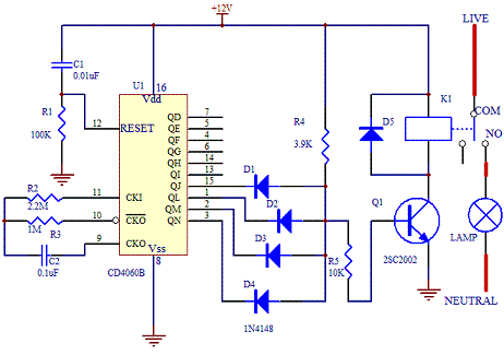
Anyway, this circuit at http://www.electronics-project-design.com/electronictimerswitch.html seems to almost fit the requirements quite nicely, and is based on easily swappable and cheap components. It can be upgraded if necessary (e.g. the oscillator could be crystal based for better accuracy)

Timer circuit

The IC is a 14-bit binary counter, and is clocked by the RC oscillstor made from pins 9, 10 and 11. The values of the RC components set the clock period (more info in the C4060B datasheet)
To set the on/off period, you need to AND the correct pins together for your desired ratio. Say you set the timing so the the count reaches 2^14 in 60 minutes, this means the clock is 2^14 / 3600 = ~4.55Hz.
Now you want the timer on for 7.5 minutes of this hour, so you need it on for 2^14 / 8 = 2048 counts. So to calculate the bits we need to AND together:

2^14 - (2^14/8) = 14336 to binary equals:

11100000000000

So bits 13, 12 and 11 need to be ANDed together (the same as the schematic above just without D1)
This is just a rough example, other timings can be achieved by calculating accordingly and you could use proper AND/OR gates, or a comparator IC or cascade another counter IC or... if you want to improve the design. Hope this helps to get you started.

\$\endgroup\$
10
  • \$\begingroup\$ Charging the internal batteri from 12V supply is handled in the tracker. It can also charge from USB. I estimated similar to you, and the energy consumption alone should not drain the car battery in 2 weeks. I would not expect the charger efficiency to be <50% (when charging) so this led me to think that it has a large standby consumption when connected to an external power source. I have tried powerdown of the tracker for 15-20 minut intervals, but it is bad with regards to our use of the car, and starting and reconnecting the GSM actually draw more power which outweigh the savings. \$\endgroup\$
    – Hans
    Commented Jun 30, 2013 at 15:44
  • \$\begingroup\$ I was not hinting at a 50% charger efficiency, it's probably ~80%. However, there are probably other drains on the battery other than the the tracker which may help towards halving the initial estimated time, and also the state of the battery has to be taken into account. You could test for this by disconnecting the tracker and using a multimeter to test the battery drain (with ignition off) \$\endgroup\$
    – Oli Glaser
    Commented Jun 30, 2013 at 16:29
  • \$\begingroup\$ I cannot think of any other drain than the clock, and when I tried to measure current drawn from the battery w/o the tracker I didn't see any. When running off the internal battery, the tracker shuts down (or disconnects) when the voltage drops to approx. 3.2V (from around 4V), so it probably doesn't use all of the 1.1Ah. One reason I want to do the experiment on a car and not on the desktop is that I don't have any good means of measuring the total energy drawn by the tracker. The current is small, and it is not constant. The other method allow me to check the car battery over several days. \$\endgroup\$
    – Hans
    Commented Jun 30, 2013 at 21:42
  • \$\begingroup\$ Ah I see, you want to try and build a picture of the total energy consumption. I'll think about an easy circuit for the switching you describe - as well as this (or instead of), what about a simple(ish) circuit to log the power consumption? How comfortable are you with microcontrollers? \$\endgroup\$
    – Oli Glaser
    Commented Jun 30, 2013 at 22:31
  • \$\begingroup\$ First of all I want to reduce the consumption of the tracker setup. Without it, the car battery lasts well. The tracker report on the supply voltage once per hour, so I have some idea about the status of the car. That does not help in reducing the consumption. I could build something bulky for testing with an Arduino, a relay and an additional battery and try to fit it into the car dashboard, but I would prefer a simple solution that can be replicated for cheap if it works well. I have some microcontrollers on my work desk but they are still only on my to-do list in terms of programming them:( \$\endgroup\$
    – Hans
    Commented Jul 1, 2013 at 5:54

Your Answer

By clicking “Post Your Answer”, you agree to our terms of service and acknowledge you have read our privacy policy.

Not the answer you're looking for? Browse other questions tagged or ask your own question.