1
\$\begingroup\$

My objective is to generate an interrupt on an Atmega328P processor every second or so, using substantially less average current consumption than the inbuilt watchdog timer.


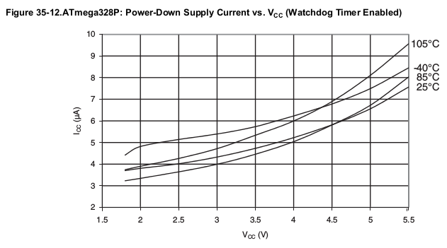
You can see from the datasheet that with the watchdog timer enabled the current consumption at 5V and 25 °C is around 6.5 µA:

Current with watchdog enabled

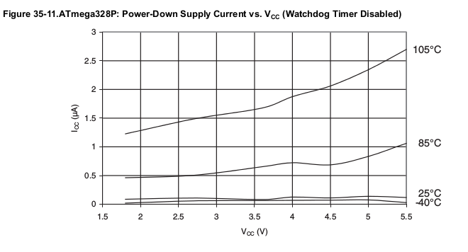
With it disabled we are down to around 100 nA:

Current with watchdog disabled

Something in-between, say 1 µA, could result in substantially longer running from a battery, but still allow the processor to wake up and check for things like the current light level, temperature, that sort of thing.


I've been experimenting with this:

Watchdog circuit

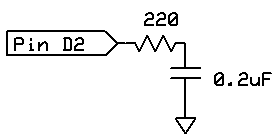
The idea is that the capacitor will be charged quickly (50 µs) through the resistor which limits current to around 22 mA (assuming 5V operation for the moment). The output then goes to high-impedance, and we wait for a falling interrupt to wake the processor and deal with it.


Test code:

const byte capacitor = 2;
const byte LED = 13;

volatile byte fired = true;

void myISR ()
  {
  digitalWrite (LED, HIGH);
  fired = true;
  }

void setup() 
  {
  pinMode (LED, OUTPUT);
  attachInterrupt (0, myISR, FALLING);
  }

void loop() 
{
  if (fired)
    {
    delay (1000);
    digitalWrite (LED, LOW);
    digitalWrite (capacitor, HIGH);
    pinMode (capacitor, OUTPUT);
    delayMicroseconds (50);
    EIFR = bit (INTF0);  // clear flag for interrupt 0
    pinMode (capacitor, INPUT);  // high impedance
    digitalWrite (capacitor, LOW);
    fired = false;
    }  // end of if fired
}

This code does not have the sleep code in it, it isn't really relevant to the question.


Testing indicates that this gives a delay of about 970 ms from when I start charging the capacitor, to when the interrupt fires, which is about what I want.


The questions

  • Is this the best way (or at least a reasonable way) of generating a timed wake-up signal with minimal power consumption?

  • I calculate that the average consumption would be:

    22 mA / (1 / 50 µs) = 1.1 µA
    

    Does that look correct? Or is it even less as the capacitor would take less current as it charges? Like, approximately half that?

\$\endgroup\$
3
  • \$\begingroup\$ With your scheme, the falling edge time is likely to vary a lot, depending on the temperature of the uC, dirt on the board, etc. There isn't even really a guarantee that the falling edge will happen at all, since there could be some condition where leakage from VCC dominates over leakage to ground when the uC pin is in high-Z state. \$\endgroup\$
    – The Photon
    Commented Sep 15, 2015 at 1:42
  • \$\begingroup\$ I'm not too worried about the exact accuracy. I could always check a RTC chip from time to time. As to the point about no falling edge, would it help to have a pull-down resistor? I tried 1 M just then, and that drastically reduced the time interval (to 50 ms). There is another related question where Olin Lathrop said he made a timer with "a few transistors and high-value resistors and capacitor". However there are no other details. \$\endgroup\$ Commented Sep 15, 2015 at 1:51
  • \$\begingroup\$ The 970 ms you are measuring implies a leakage equivalent to about 4.3 megohms; adding an additional lower-value resistor will at least halve the decay time. But it should also make the decay more consistent. \$\endgroup\$
    – The Photon
    Commented Sep 15, 2015 at 2:03

2 Answers 2

1
\$\begingroup\$

Not only is this scheme supply voltage dependent as you've noted, but it also depends on the precise atomic-level geometry of the input transistors, specifically their leakage and voltage threshold.

If you want even lower power than the WDT then you should consider using a watch crystal and the asynchronous timer. The datasheet puts typical power consumption for this method at 0.8µA at 1.8V and 0.9µA at 3V, making an extrapolation of 1.1µA at 5V very reasonable.

\$\endgroup\$
1
  • \$\begingroup\$ Well, now I feel like a dill. For one thing, my circuit was basically measuring a floating input, which is a silly idea. Also I had code for doing exactly what you suggested here. I had forgotten that it has quite good performance. I measured 1.46 µA current consumption if running from 5V power supply, and 1.1 µA if running from 3.3V power supply. Still, I am interested in Olin Lathrop's claim that "Back when built-in watchdogs took a few µA, I made a external one that used only a few 100 nA." \$\endgroup\$ Commented Sep 15, 2015 at 2:18
0
\$\begingroup\$

Consider using a separate processor, such as the PIC12LF1571. Its current consumption is:

Typical sleep current is 30 nA @ 25 °C (maximum 270 nA @ 85 °C)
Typical WDT takes an additional 550 nA @ 25 °C (maximum 750 nA @ 85 °C)  

Total: typical 850 nA @ 25 °C, and maximum 1.02 µA @ 85 °C.

The WDT can time anything from 1 ms up to 256 (1 s is one of the choices). All you need to add is a decoupling cap. It is a 3.3V part.

The chip costs around 75 cents and comes in either 8-pin DIP, SOIC, or MSOP packages.

\$\endgroup\$

Your Answer

By clicking “Post Your Answer”, you agree to our terms of service and acknowledge you have read our privacy policy.

Not the answer you're looking for? Browse other questions tagged or ask your own question.