0
\$\begingroup\$

I'm planning to make a little device that detects when a path of laser light is broken. The device will have 3 photo-resistors and three corresponding lasers. Like so:

|-(PHR)    <---(Laser)
|
|-(PHR)    <---(Laser)
|
|-(PHR)    <---(Laser)

I know that the environment that this will be in has variable non-laser light, which may throw off the sensors. So I want to design the circuit so that a trigger is set off when one of the three resistors is substantially more resistive than the others. I can't seem to figure out how to implement this circuit though. Does anyone have any useful information for this? I understand basic DC and AC circuits, but I guess I'm a little rusty.

Edit: I'm assuming this can be done with passive components. Not that it's a strict requirement, but it's the reason I'm asking. If this can't be done with passive components, then it's suffice to say so or explain why.

\$\endgroup\$

2 Answers 2

1
\$\begingroup\$

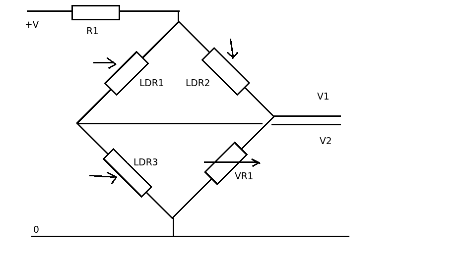
You might consider connecting the LDR's in a bridge arrangement.

enter image description here

As you are only interested in the event of one of the LDRs going 'high resistance' this arrangement would compensate for variation in background light.

Under normal conditions VR1 would be adjusted so V1 and V2 where the same. If LDR1 went high V2 would go LOW. If LDR3 went high V2 would go high. If LDR2 went high V1 would go low.

An op amp comparator, such as as lm339 could be used to detect the change.

\$\endgroup\$
1
  • \$\begingroup\$ thank you. That's exactly the kind of solution I was looking for. \$\endgroup\$
    – tay10r
    Commented Jul 17, 2013 at 6:50
2
\$\begingroup\$

At a high level:

  • Each LDR is set up as part of a voltage divider from supply to ground, with a fixed resistor as the other half of the divider, output from the junction
  • High input impedance difference amplifier between LDR1 and LDR2 outputs, and between LDR2 and LDR3 outputs
  • Analog adder, or OR gate, fed by the above two diff-amp outputs
  • If this results in a non-zero output, then either LDR1 and LDR2 differ in reading, or LDR2 and LDR3 differ in reading, or both.

The difference amplifiers would need to be attenuated, to avoid very slight differences which are always present, from triggering this system.

Part numbers and specifications would be decided based on the actual thresholds and LDR parameters.


Update: To support the edit on the question.

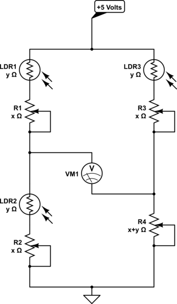
Use a Wheatstone Bridge:

schematic

simulate this circuit – Schematic created using CircuitLab

If any single arm of the Wheatstone Bridge varies in resistance from the others, there will be a perturbation in the voltage reading.

The initial effort to balance the bridge will be substantial, though.

\$\endgroup\$
5
  • \$\begingroup\$ Is there a solution with only passive components? not that it's a requirement, but I can't help but think that I'm missing out on some clever, minimalistic method \$\endgroup\$
    – tay10r
    Commented Jul 17, 2013 at 6:34
  • \$\begingroup\$ @TaylorFlores You could just set up the 3 LDRs as a Wheatstone bridge with the fourth arm being a trim potentiometer, but I suspect balancing the bridge for base condition will be a PITA. \$\endgroup\$ Commented Jul 17, 2013 at 6:44
  • \$\begingroup\$ I read your link, that's what I'm looking for, thanks! \$\endgroup\$
    – tay10r
    Commented Jul 17, 2013 at 6:53
  • \$\begingroup\$ @TaylorFlores Honestly, once you try balancing the bridge at your expected ambient-light operating point, you will curse the day you ever saw that link. It's a minimalistic solution in theory, but a fairly impractical one in reality. \$\endgroup\$ Commented Jul 17, 2013 at 6:55
  • \$\begingroup\$ okay, I probably won't use that solution then \$\endgroup\$
    – tay10r
    Commented Jul 17, 2013 at 19:53

Your Answer

By clicking “Post Your Answer”, you agree to our terms of service and acknowledge you have read our privacy policy.

Not the answer you're looking for? Browse other questions tagged or ask your own question.