Some Arduino starter-kit projects show the resistor placed before the anode of a LED, coming from output, and others show it after the cathode, going to the ground. Is there any difference? Why?
-
\$\begingroup\$ @Qmechanic you are right, but that didn't show up on StackExchange list because it's on Area51. \$\endgroup\$– rafb3Commented Nov 25, 2013 at 15:53
-
\$\begingroup\$ It doesn't matter, but you'll see the resistor most often at the anode side. Just a convention. \$\endgroup\$– radagastCommented Nov 25, 2013 at 17:33
3 Answers
There's no difference.
One of the basic principles of electric current is that the same current flows through all elements that are arranged in series.

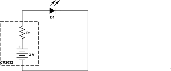
simulate this circuit – Schematic created using CircuitLab
The purpose of the resistor is to limit the current, it doesn't matter in which part of the circuit it is located.
In the case of throwies, the internal resistance of the coin-cell battery is used as a current limiting resistor.

Usually as RedGrittyBrick said it doesn't matter. You have non-reactive components (ideally, which is pretty close to reality) thus any current flowing into the diode/resistor must flow out, thus current would be limited equally well by having the resistor on either the anode or cathode side.
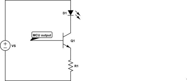
However, there are designs for driving LED's using transistors where choosing where you place your resistor does matter. For example, sometimes people will use a BJT transistor to allow for higher current drives through the LED because micro controller pins are limited to low current outputs. By cleverly placing the resistor it can serve multiple functions at the same time, thus allowing you to reduce the part count and save some money/space.

simulate this circuit – Schematic created using CircuitLab
In the above schematic we are using the resistor R1 to both limit current flowing through the LED as well as limiting the base current (current from MCU output to R1). If we instead moved R1 above Q1 or even above D1, we would have to add an additional resistor between MCU output and Q1 to limit the base current. This is an extra part we would have to have in our design meaning extra cost and space.
It's unclear from the original question if the kit/tutorials you're using have this type of LED driving circuit. It's not unreasonable because a typical small LED's current is below the limit of being safe to drive directly from the MCU, but is slightly worry-some if you have a lot of other stuff going on. Just be aware that sometimes the arrangement of parts does matter, and other times it doesn't.
Is the cost significant? It really depends. Resistors are really cheap (unless you have super high requirements), and a resistor generally doesn't take up a lot of space. It also gives you better control over the two different currents, but it isn't free.
-
1\$\begingroup\$ The downside of that arrangement is that if a collector to base short should occur in the drive transistor and you drive the MCU output LOW, you have just destroyed your microcontroller. \$\endgroup\$– MattyZCommented Nov 26, 2013 at 6:15
-
1\$\begingroup\$ The first word in your answer, "usually" is inaccurate. It never matters. When you begin elaborating you're describing a completely different circuit, which is irrelevant to the question. \$\endgroup\$– radagastCommented Dec 2, 2013 at 14:37
-
\$\begingroup\$ It would matter in an RF circuit :p. \$\endgroup\$– scldCommented Dec 2, 2013 at 16:26
No there is not any difference usually a resistor is connected in series with the LED to limit the current. Whether it is connected to anode or to cathode it doesn't make any difference. Resistor is just connected in 'series with the LED'.
