3
\$\begingroup\$

I'm working on a very basic 4x4x4 LED cube. The LEDs are single color LEDs (blue, in my case) with a max forward voltage of 3.2v. I understand (conceptually) everything about how the cube functions with the exception of one thing: the transistors I need to control each horizontal "layer" of the cube. I've read countless threads, posts, and instructables on this, but yet I'm still confused on it. I'm hoping someone can help me out.

Some basic info:

  • Using a standalone ATMEGA328
  • 16 vertical cathode columns driven by two 74HC595 shift registers
  • 4 horizontal anode layers

Why?:

  • To learn & understand multiplexing with shift registers better
  • To learn about PCB creation for small projects
  • To have a cool thing to play with

I have the following schematic (please be gentle, I'm still learning how to make schematics): 4x4x4 LED Cube schematic
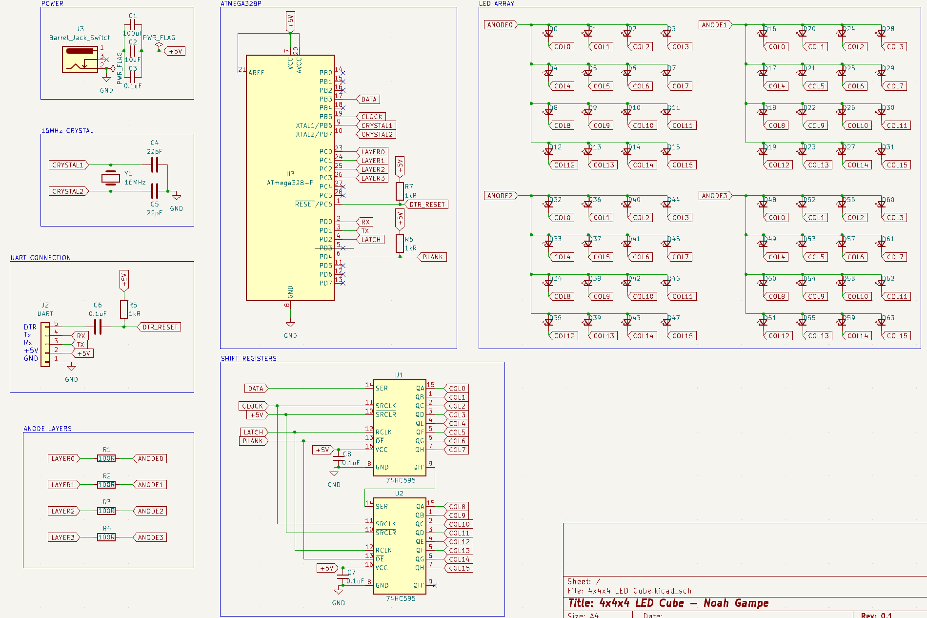
My confusion is how to control the 4 anode layers. I have seen many people using NPN BJT transistors, but they tend to have common cathode layers instead of anode - which leads me to believe that I need 4 PNP transistors? Is that logic correct?

My understanding is that at any given time, only one layer will ever be "lit" at once, meaning a maximum of 16 LEDs will be on. If each LED has a forward current of 20mA, then at most I need a transistor that can handle 16 * 20mA = 320mA at once. Assuming I was right about needing a PNP transistor, would a 2N2907 PNP transistor be fine? It can handle 600mA (seems like overkill, but it's what I currently have).

If that is sufficient, how do I go about connecting it in my schematic? I'm assuming it would be placed somewhere in the "Anode Layers" block of my schematic. I'm unsure of how to wire it up to the rest of the circuit. If possible, can someone help me with that? I'm sure there needs to be another resistor in there, but as for where, I'm unsure. Thank you!

\$\endgroup\$
4
  • \$\begingroup\$ Why aren't you using a common cathode array? In any case, you need one resistor per column. \$\endgroup\$
    – Mattman944
    Commented Dec 10, 2023 at 21:06
  • \$\begingroup\$ @Mattman944 Well, I've seen a lot of questionable instructables on LED cubes, and I've looked a lot at Kevin Darrah's 8x8x8 RGB LED cube (which uses common anode RGB LEDs) and it just made sense to me to do it this way. I initially was trying to make an RGB cube, but that was far more complicated, and so I'm trying this single-color cube - but I guess I had all the RGB information still in my head so I stuck with it. \$\endgroup\$
    – n0ah
    Commented Dec 10, 2023 at 21:21
  • 1
    \$\begingroup\$ The PNP transistor is not a problem. One problem is the shift register. If you assume 20mA per LED, that's up to 160mA supply current per shift register. Unfortunately the absolute maximum rating for supply current for a 74HC595 is 70mA. And your DC barrell plug capacitors are incorrectly wired so it won't power the board. \$\endgroup\$
    – Justme
    Commented Dec 11, 2023 at 6:18
  • 1
    \$\begingroup\$ Your schematic has an mistake, the filter caps (C1, C2, C3) need to be connected in parallel with the atmega chip, instead of in series \$\endgroup\$
    – Ferrybig
    Commented Dec 11, 2023 at 9:48

1 Answer 1

3
\$\begingroup\$

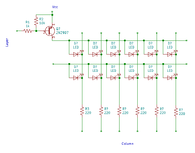
Here is how I would do it with a PNP driving the layers, assuming that the GPIO voltage and Vcc is 5 volts.

enter image description here

Note that both the Layers and Columns are using negative logic. A logic 0 activates the layer or column.

The 2N2907 is a reasonable choice. But, you not only have to consider the current, you also need to consider the power dissipation. So, you should learn how to calculate the temperature rise.

Edit: Justme pointed out a serious issue, the 74HC595 can only drive 70 mA total on all outputs. You should target 5 mA for your LEDs. Always leave margin, 50% if possible, a little less if necessary. After you scan the 4 layers, you will have about 1 mA average, this may be bright enough for your purposes, you need to run some tests.

0.005 A * 16 cols * 0.3 Vdrop = 0.024 W

0.024 W * 438 degC/W = 11 degC temp rise

You want to avoid parts that are hot enough to burn you, I use a goal of 50-60 degC max. At 60 degC, you can react fast enough to remove your hand before you are burned. At 70 degC, you can't.

For transistor switches you want to saturate them hard, so you never use the typical beta. Use about 20-25. So, you want about 5 mA base current. R1 about 1k.

R2 isn't absolutely necessary, but it is good practice to include it. It will help prevent noise on Vcc from spuriously turning on the transistor.

R3 sets the LED current. You should measure your LED voltage drop at 5 mA. Then calculate the value for R3. If the LED drops 3.2 V, the transistor drops about 0.3 V, and the shift register drops 0.2 V ...

5 V - 0.4 V - 3.2 V - 0.2 V = 1.2 V drop across the resistor. Divide by 5 mA. The closest value is 220 ohms.

To increase the column drive current, you could add a buffer such as a 74AC244.

Or you could use a TLC6C598, a shift register designed to drive LEDs, but it is only available in surface mount.

Whenever possible, you want to breadboard or simulate your circuit before committing to a PWB. I have been doing this for 50 years and I would still breadboard a 2 x 2 matrix before committing to a PWB.

You should also consider using an IC designed to drive an LED matrix such as the MAX7219. Note that your software will be completely different, it does the scanning for you.

Can I use a MAX7219/7221 chip to drive 16 common anode RGB LEDs?

\$\endgroup\$
2
  • \$\begingroup\$ Thank you for taking the time to give so much detail! It's very helpful, and very much appreciated! I have also started looking at the MAX7219 because so many people on the internet have told me that the way I've been approaching it is all wrong :( - if I used the MAX IC, I'd have to remake the cube where each column was the LED anodes, and each layer was the LED cathodes - am I understanding that correctly? \$\endgroup\$
    – n0ah
    Commented Dec 12, 2023 at 0:58
  • \$\begingroup\$ The MAX7219 is designed to drive an 8 x 8 matrix. You won't be able to have 16 LEDs with common anodes or cathodes on the same layer. \$\endgroup\$
    – Mattman944
    Commented Dec 12, 2023 at 22:32

Your Answer

By clicking “Post Your Answer”, you agree to our terms of service and acknowledge you have read our privacy policy.

Not the answer you're looking for? Browse other questions tagged or ask your own question.