0
\$\begingroup\$

I'm looking for a little help understanding this circuit:
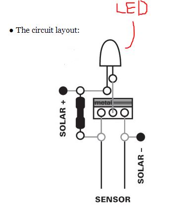
Circuit image

http://i1316.photobucket.com/albums/t607/blueturnsred1/Capture_zps5150bde6.jpg

Details of the circuit:

1 IRF510 Power MOSFET N-Channel

1 1M Ohm Resistor

The sensor is made from plaster of paris

About the circuit:

Basically what we have is a mosfet connected to an LED and a 6 volt solar cell. The sensor is a piece of plaster of paris with two nails in it. The whole kit can be seen here:

http://technologywillsaveus.org/resources/thirsty-plant/

The idea behind the circuit is that you put it in a plant's soil, and when the plaster of paris "sensor" dries out the led comes on, and you know it's time to water the plant.

I have been trying to wrap my head around how this switch works. What I have been able to understand so far is that in a typical switching application. when five volts is applied to the gate of the the MOSFET it will switch on and allow the circuit to function.

The way I think that this circuit works is that the current is shorted through the "sensor" when the plaster of paris is wet. I believe this keeps the current from going to the gate of the MOSFET, and keeps the LED off. Then when the "sensor" dries out the current goes to the gate and switches the MOSFET on.

Can anyone tell me if I am on the right track?

I have read a lot of tutorials, but I can't find anything that will help me further understand this.

\$\endgroup\$

1 Answer 1

2
\$\begingroup\$

The gate of the MOSFET can be regarded as a pure voltage sensor which doesn't draw any current. (The only time this reasoning doesn't apply is in a high speed or high frequency application; whereas here, the signal from the sensor is changes slowly so that it is DC for all intents and purposes).

Note that the sensor is in series with another resistor. The two form a voltage divider. The resistance of the plaster of Paris is expected to vary with moisture content and change the voltage at the midpoint of the voltage divider. If the sensor dries up completely, it basically does not conduct, and then the other resistor "pulls up" the voltage at the MOSFET's gate right to the positive supply voltage.

There is no diversion of current; the gate voltage alone controls the transistor's channel.

\$\endgroup\$
3
  • \$\begingroup\$ Be careful not to confuse MOSFETs with BJTs, it's BJTs which are controlled with a current to their base, while with MOSFETs it's a voltage to it's gate. Note: This is an addition to Kaz's statement, this is not directed at you Kaz! \$\endgroup\$
    – gbmhunter
    Commented Dec 5, 2013 at 1:44
  • \$\begingroup\$ @gbmhunter I'd never interpret it that way even without the note. ;) \$\endgroup\$
    – Kaz
    Commented Dec 5, 2013 at 1:52
  • \$\begingroup\$ amazing! thank you for shedding some light on this. \$\endgroup\$
    – user109982
    Commented Dec 5, 2013 at 2:11

Your Answer

By clicking “Post Your Answer”, you agree to our terms of service and acknowledge you have read our privacy policy.

Not the answer you're looking for? Browse other questions tagged or ask your own question.