1
\$\begingroup\$

I'm using a sensor that has a specific connector, which outputs signal with 18-gauge wires, such as these:
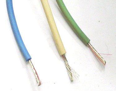
enter image description here

And I need to connect it to standard male header pins, where cables such as these would connect to (sorry, I don't know the name in english):
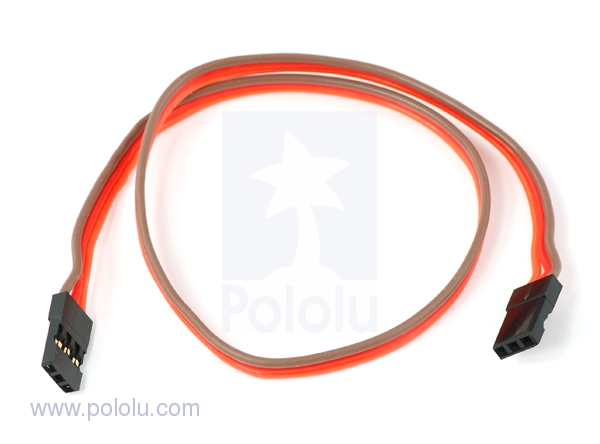
enter image description here

The sensor is going to be connected to a board in an UAV, so the connection needs to be firm, as the UAV would be flying around. I will also need to power the sensor from the board, so there would be:

  • A ground and a output wire from the sensor to the board

  • A ground and an +5V wire from the board to the sensor

  • The sensor wires are all 18-gauge, and the board housings are all smaller (same size as in the picture)

    Here are some ideas I've had:

Make a separate adaptation board and use a phoenix-type connector.

This board would have a 3-pin female cable such as the picture above, and that would go into the board.

Use some sort of molex-type connector.

This would have no board, but I'm not too familiar with making these types of connections.

So I would like inputs on my ideas to make this interface, as well as your own ideas that would allow me to make a stable connection occupying as little space as possible.

Please let me know if I'm not clear on anything.

EDIT: Here's a schematic for clarity. I'm just looking for suggestions on how to do the ? part, in order for a secure and safe connection. I am also not sure if it's good practice to connect both grounds on the board or if I can just get away with one.
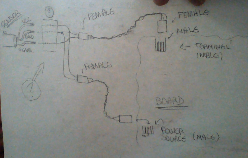
\$\endgroup\$
7
  • \$\begingroup\$ Will the sensor wires plug directly into the UAV board or are you wanting to bring wires out of the sensor and wires out of the board, connecting in the middle? If directly into the board, do you want the ends of the sensor wires to terminate male or female? \$\endgroup\$
    – mikeY
    Commented Jan 27, 2014 at 17:20
  • \$\begingroup\$ Can't you just solder the connector on? Cover the joints with heat-shrink...can't imagine anything smaller or simpler. \$\endgroup\$
    – Phil Frost
    Commented Jan 27, 2014 at 17:33
  • \$\begingroup\$ @mikeY: I am inclined to do it on a board. If on a board, I don't know how I am going to attach them, and want suggestions on that. If not on a board, then I have no idea how I would work that, and would also like suggestions =S \$\endgroup\$
    – triplebig
    Commented Jan 27, 2014 at 17:51
  • \$\begingroup\$ @Phil: I can't solder directly to the board, and I would also want to be able to remove the sensor from the board. Sorry if I misunderstood your suggestion \$\endgroup\$
    – triplebig
    Commented Jan 27, 2014 at 17:54
  • \$\begingroup\$ @triplebig no, I mean solder the sensor to the connector, which then connects the board. Ostensibly the problem here is that you can't find a connector that will take wires as fat as 18 ga, so solder thinner wires on the fat wires, and then the thinner wires fit in the connector. \$\endgroup\$
    – Phil Frost
    Commented Jan 27, 2014 at 18:40

1 Answer 1

1
\$\begingroup\$

I think all you want to do is solder some male header pins on the wires out of your sensor, and then make a connector wire for your board(s) with some female pins soldered on both ends. Maybe one end of the connector has a solid block of pins and the other end is split to hook up in two places.

I think you are overthinking it and making it more difficult than it really is. I think regular solderable header pins should be sturdy enough for a UAV. You could go all Molex or something but I don't think you need to.

\$\endgroup\$

Your Answer

By clicking “Post Your Answer”, you agree to our terms of service and acknowledge you have read our privacy policy.

Not the answer you're looking for? Browse other questions tagged or ask your own question.