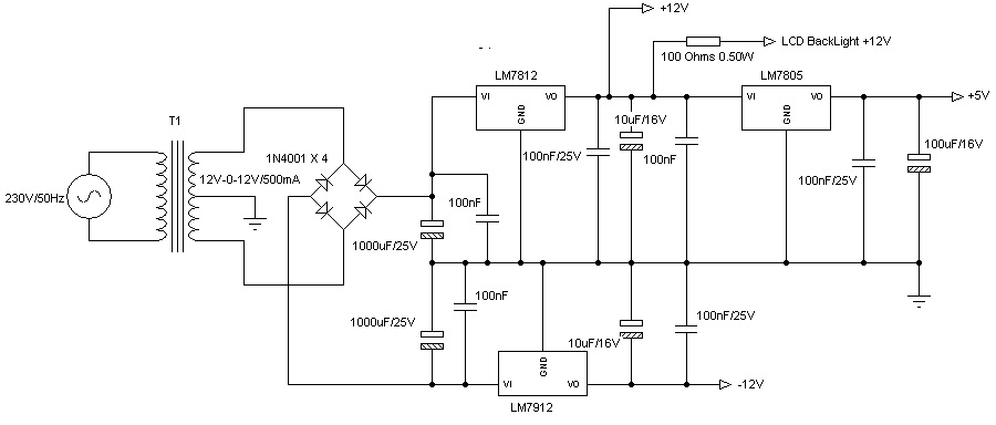
In the below circuit, capacitors with several values are utilized (Eg: why 1000μF and 100μF capacitors are chosen). Could you please let me know how to identify the required values of the capacitors and the reason to have a electrolytic capacitor and a normal capacitor in parallel.
-
\$\begingroup\$ A portion of your question is answered here: electronics.stackexchange.com/questions/70245/… \$\endgroup\$– DavidCommented Mar 3, 2014 at 9:42
-
\$\begingroup\$ There is also this excellent set of answers: electronics.stackexchange.com/questions/37672/… \$\endgroup\$– DavidCommented Mar 3, 2014 at 9:42
-
\$\begingroup\$ And here for some basics: electronics.stackexchange.com/questions/2272/… \$\endgroup\$– DavidCommented Mar 3, 2014 at 9:43
-
\$\begingroup\$ It may be worth noting that while a larger smoothing capacitor results in less ripple voltage, it will result in larger surge currents on power-up and larger peak repetitive currents. \$\endgroup\$– TutCommented Mar 3, 2014 at 13:10
1 Answer
When the bridge rectifier converts AC to DC it does so by ensuring that the most positive voltage from the transformer is routed (via the diodes) to the positive DC feed to the circuit. This charges the 1000uF capacitor up to approximately the positive peak of the AC voltage.
What happens next is that the AC voltage starts falling down from the peak and the 1000uF cap is left charged up. Not until the next peak of the AC comes along (this time on the other AC wire from the transformer) is the capacitor recharged.
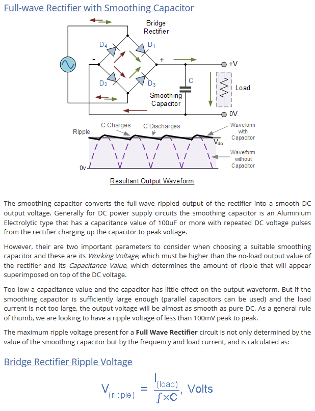
The capacitor is charged over a period of a few milli-seconds and, becomes slightly discharged by the regulators and load current. This is why those capacitors are so large - they have to supply a near constant voltage between re-charge pulses delivered through the bridge rectifier. Here is a good article that explains how to calculate the capacitor.
The 1000uF caps are used as bulk energy storage devices and they need to be big because of the duty cycle of charge and discharge. But a big cap like 1000uF will have considerable internal resistance (maybe 1 ohm) and inductance (maybe several tens or hundreds of nano henries). The R and L do not make this capacitor very good for a linear voltage regulator so, a much smaller capacitor (like the 100nF) is applied in parallel - the 100nF might have tens of mill ohms series resistance and inductance of tens of micro henries at the most - together, the 1000uF and 100nF make a good all-round combination.
-
\$\begingroup\$ The ripple limits is one of the possible method to calculate the capacitor needed, considering ideal rectifier (Ri=0) and finite capacitor. Two assumptions should be there: the capacitor discharging time is the maximum possible (10ms) and for a non-zero Ri the Ri-C combination acts as a secondary filter that reduces the ripple. The semi-graphical Schade method is one that used for many decades in designing unregulated PSU with capacitive input filters. \$\endgroup\$– GR TechCommented Mar 3, 2014 at 16:56
-
1\$\begingroup\$ This answer is potentially dangerous, since it ignores the ripple current. As the bulk capacitance goes up, so does the ripple current. The peak current rating of the rectifying diodes needs to be accounted for, as well as the impact of ripple current on the heating of the transformer windings. \$\endgroup\$ Commented Mar 3, 2014 at 23:35