1
\$\begingroup\$

I'm trying to do something that seemed simple at first but is proving to be complicated (shocker, right?) I want to power a super bright LED (Luxeon K2, Cool White, 350mA. It's discontinued, but the datasheet is still the first hit on Google) using a 3.7V LiPo battery from SparkFun. The instructions I have for the LED tell me to regulate the voltage with an LM317 voltage regulator.

Problem being, the LED has a forward voltage of somewhere between 2.8 and 3.4V, and the LM317 appears to eat up too much voltage to make that possible. I don't want to wire 2 batteries in series because my enclosure is pretty small, and there's no space for another battery.

So I found this charging/step-up breakout board that can bump me up to 5V. I'm extremely new to electronics and this is my first project where exact voltage/current/resistance are an issue. My question is threefold:

  1. If I'm using the breakout board to regulate my voltage, do I even need the LM317? Or can I just use resistors to get the current to where I want it?

  2. How can I know what the current will be when it comes out of the breakout board? The datasheet for the voltage regulator on the board seems to say I can program the output current to anything between 15 and 500mA, but I don't understand how to do it.

  3. Am I right about needing the step-up? Or could I potentially just run this with the battery and the LM317?

I'm doing this project in order to learn, so I would prefer answers that show me how to figure this out for myself as opposed to just doing it for me.

\$\endgroup\$
3
  • \$\begingroup\$ I'm sure you mean mA and not uA... \$\endgroup\$
    – horta
    Commented Apr 24, 2014 at 17:48
  • \$\begingroup\$ Right you are. Fixed. \$\endgroup\$
    – Tack
    Commented Apr 24, 2014 at 17:55
  • \$\begingroup\$ Voltage regulators like LM317 should be avoided when using batteries. Otherwise you lose a lot of valuable power in the regulator. \$\endgroup\$
    – Al Kepp
    Commented Apr 25, 2014 at 0:55

4 Answers 4

1
\$\begingroup\$

I would simply find a voltage regulator or even better, a current regulator that has a low drop-out voltage. In that way, you don't need the sparkfun board and you can control your LED without having to boost it and then regulate it back down. That seems like a lot of effort and wasted energy going through two stages instead of one since your battery can handle the voltage requirements of the LED.

\$\endgroup\$
0
1
\$\begingroup\$

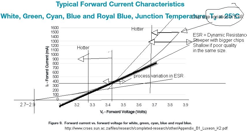
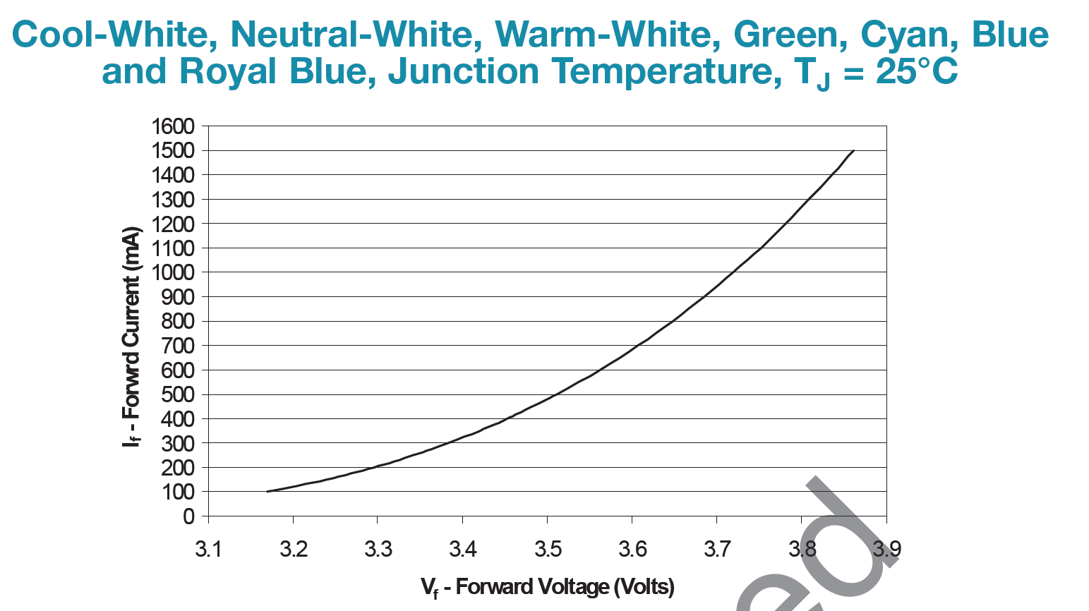
Based on this datasheet, it appears the LED typically needs 3.4V at 350mA.

enter image description here

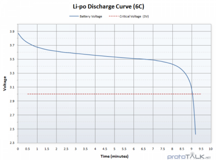
Based on this discharge curve:

enter image description here

It looks like the battery voltage itself should work if we can make a linear current sink or source with 100mV of drop. That's not too difficult with an op-amp, transistor and resistor, plus a reference.

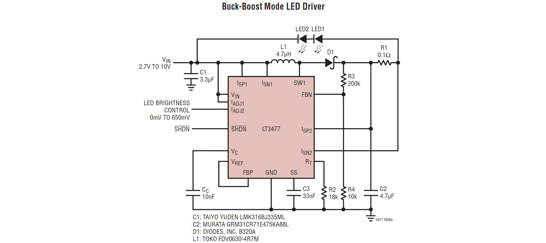
Another possibility, not to be excessively sneered at, is to use a 'canned' solution such as a buck-boost LED driver chip. This reduces your work to interpreting the data sheet and wiring up a tiny package.

enter image description here

You should also consider how to protect the battery from excessive deep discharge.

\$\endgroup\$
0
\$\begingroup\$

Use a buck/boost converter.

A basic buck is a 4-component analogue circuit, but fully-featured (and integrated) ICs are available.

Were the LED driving not the focus of your project, I would recommend a product like the BuckPuck, given the low cost versus the large time investment of designing your own.

\$\endgroup\$
0
\$\begingroup\$

enter image description hereThere are many solutions that tradeoff complexity vs constant brightness vs precision.

I will propose the easiest solution which you suggested by choosing series R.

You will need a bunch of 1 Ohm resistors in 1/2W so that you can add 0.5 , 1, 2 Ohm.

The ESR or dynamic resistance spec has no tolerance on these old parts ., but it is given for LK2-xx12-xxx at 350 mA as 1.0 Ohms typical Dynamic Resistance (ESR) with Vf 2.79~3.42~4.23 (Min~typ~max) Which means the ESR can easily range from 0.4 to 5 Ohms. Newer parts are expected to be on the low value range (low ESR) high ones are marginal quality and will run very hot.

  • design in good heat sink. 40- 50deg/W = Rja (junction to ambient). As you see, it can handle lots of current and if it burns your finger, it's too much. 85'C is OK, 60'C is ideal. -Just like biasing a transistor you want the current sense to indicate 350mA. By matching voltage using ESR of all resistance to add up to open circuit voltage of battery. Rtotal=LED+battery+current sense+R.

As a rule of thumb the most efficient solution for unregulated Battery drained to 0%, just when the LED string is near threshold 2.9V then use OHm's law for the difference. You will find ESR of LEDs is close to the selected R. `

For superbright 5mm LEDs this is around 15 Ohms +- 50%.

`

Next you need a shunt resistor in circuit to measure voltage drop . This could be x" of 30 gauge wire.

Measure the resistance with a known high current. And choose something like 0.1 Ohm so you expect it to be 35 mV @ 350 mA and insert it in series on the ground side for convenience of measuring current and Vf voltage and Vbat with a common 0V point. Now shoot for 3.4 V on the LED at 25'C and expect the LED to drop 0.3 V if it gets hot. This is the Schockly effect and is how all thermoeters work using diodes.

Now with a 1000% SOC 4V cell, which also has ESR in the same ballpark <1 Ohm, which you can measure and lower is a better quality battery. Battery ESR rises rapidly at 10% except the voltage drops to 3.7 quickly the 3.4 before 10% left. Consider starting at 3.7 as 90% then 3.7-3.4=0.3

Then simply use Ohms Law to account for drop voltages and start with 0.3V/0.35A =1 Ohms.

Same as LED. Matched impedance, maximal power transfer with minimum regulation error. "Joe's Law"

So this is Select on Test SOT, method 1. Dumb, but accurate . You will find the lamp gets dim as battery voltage drops to 3.5 but then you use less current and get extended runtime.

Then if you have a charge jack, use one with a ground disconnect switch when charging so you dont have to worry about frying the LED on its heat sink at 4.3V

This is just a cheap and dirty solution. But it works.

\$\endgroup\$

Your Answer

By clicking “Post Your Answer”, you agree to our terms of service and acknowledge you have read our privacy policy.

Not the answer you're looking for? Browse other questions tagged or ask your own question.