2
\$\begingroup\$

One of the most common designs for a SSB modulator (phase shift method) involves an additive mixer as the very last stage. Here is a block diagram for reference:

enter image description here

This additive mixer must provide isolation between the two inputs. I am only aware of one method for doing this, which is to "couple" the signals onto each other using well-chosen filters. Here is an example in the case of a multiplicative mixer:

enter image description here

However, this method only works when the two input signals are vastly different in frequency. How would I isolate two input signals when they occupy the same frequency band?

Given that I am dealing with RF frequencies, op-amp mixers are out of the question. Surely there is an active circuit design which provides sufficient isolation, with low distortion and able to run on a single ended supply.

\$\endgroup\$
5
  • 1
    \$\begingroup\$ How do you plan to shift every frequency in the audio range by 90 degrees - the diagram you have shown is very theoretical and is problematic in implementation - the adding of the two signals is trivial in comparison. \$\endgroup\$
    – Andy aka
    Commented Aug 25, 2014 at 11:13
  • 1
    \$\begingroup\$ @Andyaka I plan to use a modulating signal with a very small bandwidth (i.e. not voice). The diagram is just to give context - my real question is how to add these signals together even though they occupy identical frequency bands. \$\endgroup\$
    – Ryan
    Commented Aug 25, 2014 at 14:40
  • \$\begingroup\$ What carrier frequency are you considering? \$\endgroup\$
    – Andy aka
    Commented Aug 25, 2014 at 15:05
  • \$\begingroup\$ What frequencies are you targeting with this design? \$\endgroup\$
    – DakotaD
    Commented Aug 25, 2014 at 17:01
  • \$\begingroup\$ What block is the additive mixer? The circle with the plus sign in it? If so, I'm curious why isolation is an issue? Depending on the impedance requirements, the additive section could literally be two traces shorted together. You could also consider something with a 180 deg shift; such as a hybrid, balun, or a transformer like @Andyaka mentioned. These are good options because you can get both sidebands out and choose which one you want. \$\endgroup\$
    – curtis
    Commented Aug 26, 2014 at 16:55

4 Answers 4

2
\$\begingroup\$

I don't know what sort of carrier frequency you are considering but if you feel it may be too high for conventional addition via op-amps etc., you might consider using two small wideband transformers; one for each modulator and place the secondaries in series - now you get A+B and isolation.

\$\endgroup\$
2
\$\begingroup\$

Let's use proper terminolgy here, what you want is an 'adder', or 'signal combiner', to add two signals together. A 'mixer' multiplies signals, and is a component in the larger diagram you have shown.

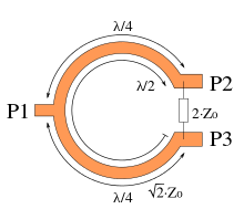
The most convenient circuit is a Wilkinson Power Combiner (wikipedia) which is used to either split one signal into two, or combine two signals into one, with isolation between the pair of component signals. A single stage Wilkinson works very well over a 10% bandwidth, and multi-stage Wilkinsons can be designed to work multi-octave.

enter image description here

image from the above linked wikipedia article

It's easy to understand conceptually what is happening. A signal entering P2 will arrive at P3 by two routes. One is through a half-wavelength of line, inverting the signal, the other is through the resistor, without inversion. The two components combine out of phase to prevent transmission from P2 to P3, and vice versa.

It's not immediately obvious that the sum port must be well matched to preserve the isolation between the component ports.

\$\endgroup\$
1
\$\begingroup\$

How about using an isolator? Also see this link. You only need one of them on either the modulator 1 or 2 branch, but using two identical units simplifies the 90° phasing requirements.

\$\endgroup\$
1
  • \$\begingroup\$ While SSB is not unheard of on higher bands, chances are this is targeting (or at least modulating an IF) below 30 MHz, where such a device would be prohibitively large. \$\endgroup\$ Commented Aug 25, 2014 at 15:33
0
\$\begingroup\$

Just a note, it is near impossible to make a single audio 90 degree phase shifter, but there are dual phase shifters which accomplish the task by phase shifting both signal paths, one keeps 90 degrees spaced from the other. Complex, but very doable. As the differential phase is the key, this works.

As to combining, another solution: active combiners could easily block leakage. In microwave range this could be difficult but not impossible. Even isolation amps followed by pads and a passive combiner would accomplish this reasonably well.

\$\endgroup\$

Your Answer

By clicking “Post Your Answer”, you agree to our terms of service and acknowledge you have read our privacy policy.

Not the answer you're looking for? Browse other questions tagged or ask your own question.