2
\$\begingroup\$

i have finished building my barebone arduino..i want to run the barebone chip with 3V battery i.e double AA 1.5 x 2= 3V..the reason i am persisting using 3V Vcc is because in our project we need to fit in the battery in a given battery slot which is very small..A 9V battery is able to fit in it..currently we are using a 9V battery but the LM7805 regulator is consuming a lot of current..which wont be efficient in future..when we want save battery power and what not..we wont be able to fit in 3X 1.5V i.e 4.5V.

anyways my question is would i able to use 3V directly on my barebone..I will replace my 16Mhz crystal clock with a 8MHz one..because 3V wont work with 16mhz..but how will i source the voltage..some assistance would be really helpful...thanks a lot...

\$\endgroup\$
8
  • 1
    \$\begingroup\$ Just connect it directly and add a small electrolytic or big ceramic capacitor, 10uF should be enough. Most ATMegas can work down to 1.8V, so ensure that the oscillator can work at 1.8V too. \$\endgroup\$
    – venny
    Commented Sep 2, 2014 at 8:54
  • \$\begingroup\$ directly as in so just connect the the Vcc wire of battery straight into 3.3Volts pin whatever that would be on the atmega barebone ..and Gnd to Gnd pin..would that be it?? \$\endgroup\$
    – riju
    Commented Sep 2, 2014 at 8:58
  • \$\begingroup\$ i just saw the arduino with atmega 328p schematic pin diagram...it just mentions Vcc.so that is just 5V so basically connect a capacitor of 10uF in series with the battery and gnd. \$\endgroup\$
    – riju
    Commented Sep 2, 2014 at 9:05
  • \$\begingroup\$ Positive battery terminal goes to VDD(=VCC), negative terminal to VSS(=GND). Capacitor goes between the two. \$\endgroup\$
    – venny
    Commented Sep 2, 2014 at 9:09
  • 1
    \$\begingroup\$ no @riju when you write a pin "HIGH" it just sources voltage and current from the VCC rail. If VCC is 3V, that is what the HIGH output will be. AREF has nothing to do with it. AREF is used for internally routing the analog ADC peripheral's reference voltage allowing you to compare certain custom input voltages giving you the full range of 1042 (10bit resolution). For example you could put a 1.24V high accuracy VREF chip onto AREF and then measure something between 0-1.24V with 1024 points, rather than 5V/1024 giving only 0-254 points. You would quadrupal your accuracy by doing so. \$\endgroup\$
    – KyranF
    Commented Sep 2, 2014 at 9:20

1 Answer 1

1
\$\begingroup\$

You can connect the 3V worth of AA batteries directly to VCC of the ATMEGA, and either use an external 8MHz oscillator (crystal or ceramic, either one works) or you can even use the internal RC osscillator with a CLKDIV2 to make your clock speed 4MHz which will work all the way down to 1.8V volts. You can also use CLKDIV settings on the external oscillators if you wanted. These options are all in the "Fuse" settings which when working with AVRs you must become familiar with. There are multiple tutorials on how to set and read fuses online, so you should be okay with some time spent researching.

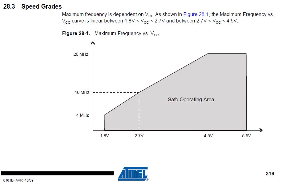
This is the chart from the ATMEGA328P datasheet (page 316) showing the VCC voltage versus acceptable frequency of guaranteed operation.

Clock frequency vs VCC voltage from page 316

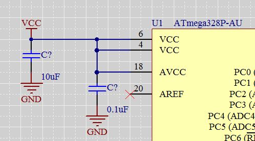
You can hook up the batteries to VCC pins of the microcontroller directly with just a power decoupling capacitor to help during digital "on/off" cycles and other forms of power spikes. Here is an example of how I do it. In your case the power net label "VCC" is literally the battery +pos terminals, and the "GND" net label is your battery -neg terminal.

Example of connecting stuff to power ATMEGA328P

good luck!

\$\endgroup\$
14
  • \$\begingroup\$ ok will surely have a look on fuse settings for the future..this schematic diagram is actually really helpful..so basically i have to remake the chip..this time getting rid of LM7805 altogether..one headache gone...in my schematic diagram only one pin 7 is Vcc and pin 20 is AVcc(Vcc)..so i short that..then i short the GND pins 8 and 22..then i connect a 10uF capacitor in series with the Vcc and Gnd...is that it?? is 0.1uF really required??? \$\endgroup\$
    – riju
    Commented Sep 2, 2014 at 9:51
  • \$\begingroup\$ "is 0.1uF really required???" - Yes, as close to the chip as possible, see the datasheets. - Remember that the battery voltage may drop over time, so try to make sure the controller can run @ 2.7V or 2.5V too (maybe even lower), for good run time on batteries. - Later, you may want to also have a look at the AVR's "System Clock Prescaler" (CLKPR), if you want to scale the system's frequency at runtime for efficiency. \$\endgroup\$
    – JimmyB
    Commented Sep 2, 2014 at 10:18
  • 1
    \$\begingroup\$ @HannoBinder Alkaline batteries can be successfully discharged below 1V, see discharge curve \$\endgroup\$
    – venny
    Commented Sep 2, 2014 at 10:24
  • \$\begingroup\$ That's right. Yet, the µC will probably not run at 12Mhz on 2.5V, while it does on 3V. On 2V only about 5Mhz will be safe. So don't go to the limit for 3V when using batteries. \$\endgroup\$
    – JimmyB
    Commented Sep 2, 2014 at 10:35
  • \$\begingroup\$ Riju if you have the DIP package version, check the datasheet and schematics for the correct pins for VCC and AVCC and all the GND pins. @HannoBinder yeah so Riji will be going to at least 8MHz, but I think 4MHz is probably good enough for whatever he/she is doing, except for perhaps high baud-rate serial comms. \$\endgroup\$
    – KyranF
    Commented Sep 2, 2014 at 10:39

Your Answer

By clicking “Post Your Answer”, you agree to our terms of service and acknowledge you have read our privacy policy.

Not the answer you're looking for? Browse other questions tagged or ask your own question.