8
\$\begingroup\$

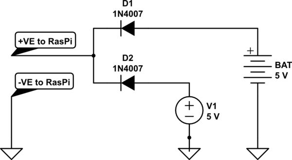
I have a Raspberry Pi that is powered by a USB cable from a Samsung charger. Now since my college has frequent power cuts, I designed a basic switch to automatically switch between a portable mobile battery and the USB power using a diode OR gate. The circuit has been taken from here and looks like this:

schematic

simulate this circuit – Schematic created using CircuitLab

So now, considering this is a very simple way of achieving my purpose, what I'd like to know is which power source is being used up when both are connected. Maybe via some LED indicator or something. The main basis for this circuit is the fact that my input V1 has a higher voltage than that coming from BAT. However, the difference between the two input sources is marginal. For example, my 2.1 A Samsung charger outputs around 5.3 V while my portable battery outputs around 5.1 V. However, this difference seems to be working fine with the circuit given here. But, to be sure, I'd like some indicator to check which input is active currently.

\$\endgroup\$
3
  • 1
    \$\begingroup\$ Measure the voltage drop across a shunt resistor located in each feed, and calculate the current flowing through them? \$\endgroup\$
    – Majenko
    Commented Sep 26, 2014 at 11:04
  • \$\begingroup\$ Could you provide some more information please? How might that be done exactly? \$\endgroup\$ Commented Sep 26, 2014 at 11:06
  • \$\begingroup\$ I am actually writing up an answer to that right now, chill out. The method of shunt resistor. \$\endgroup\$
    – KyranF
    Commented Sep 26, 2014 at 11:08

4 Answers 4

9
\$\begingroup\$

You are asking for help adding an LED indicator, but there are some other problems with your circuit. The Pi can become unstable when it is given less than 5.0 volts, and the 1N4007 diodes have a 0.8 or 0.9 volt drop. One solution is to use Schottky diodes such as the 1N5820 which have only a 0.3 volt drop.

An alternative to diodes that would provide better voltage for the Pi is this circuit:
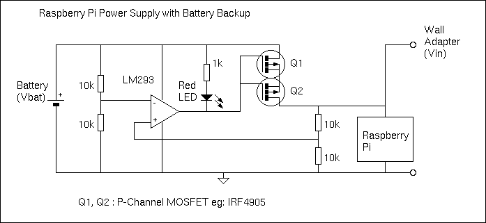
Pi Power Supply

Here a P-Channel MOSFET is used to connect the battery with the Pi when the main power supply drops. The comparator (LM293) compares the battery voltage with the main power voltage. When the main voltage drops below the battery voltage, the MOSFET is turned on and the LED is lit. The low on resistance of the IRF4905 ensures the voltage drop from the battery is below 0.1 volt when the MOSFET Vgs=-5V. The battery will power the Pi until the main voltage is restored, as the comparator will then turn off the MOSFET.

Edit: Some details.

There are some sources of error in the circuit that make it less than precise, but good enough for the purpose intended. The tolerance of the 10k resistors and the comparator offset voltage can slightly change the switching point. The 1k resistor is needed (not 220 ohm) as the LM293 cannot sink much current. The MOSFET Q1 must have a low resistance when Vgs is -5.0 volts (IRF7410 is an excellent choice but only available in surface mount). When Vbat and Vin are almost equal, noise due to variable Pi processing may cause the MOSFET to rapidly turn on and off. This may cause unwanted heat in the MOSFET. A capacitor on one of the voltage dividers will stop any rapid oscillations (but slow down the response to a declining Vin). Also, the circuit has been quickly designed and not simulated or tested...

Edit 3: A correction.

If the power supply Vin is more than 700 mV above Vbat, the integral reversed bias diode in the MOSFET will conduct and try to charge the battery from the power supply. This is probably not what you want. A Schottky diode in series with Q1 would prevent the reverse current, but this would defeat the purpose of the MOSFET! I applied the clever trick with back-to-back MOSFETs. By installing 2 MOSFETs with a common drain or common source, the body diode current leak is blocked. The pair will have twice the resistance (Rds on), but this is not important in this application.
\$\endgroup\$
6
  • \$\begingroup\$ I like this solution. Quite simple to make. Although, what might happen if both my USB and battery are almost the same voltage? (as mentioned in question) Will the comparator recognize such a minute difference in voltage? \$\endgroup\$ Commented Sep 27, 2014 at 12:23
  • \$\begingroup\$ A comparator is very sensitive. As soon as Vin drops to 1 microvolt below Vbat, the MOSFET will turn on and smoothly take over the supply of current to the Pi. \$\endgroup\$ Commented Sep 27, 2014 at 13:12
  • \$\begingroup\$ I am going to try out your version and see the results. Also, check this out. This seems far more stable, IMHO. \$\endgroup\$ Commented Sep 28, 2014 at 15:47
  • 1
    \$\begingroup\$ @KanishkaGanguly The circuit in the BMP image is a bit confusing, but the double MOSFET idea looked interesting. After checking a few other sources, I could see how it works. I have changed my circuit above. This solves a problem I have got too. Thanks for asking the question. \$\endgroup\$ Commented Oct 2, 2014 at 7:44
  • \$\begingroup\$ thanks a lot for taking the trouble to answer the question in such detail. :D I am still working on building the circuit. Getting the parts is taking time, since we have a public holiday here in India. \$\endgroup\$ Commented Oct 5, 2014 at 6:57
5
\$\begingroup\$

schematic

simulate this circuit – Schematic created using CircuitLab

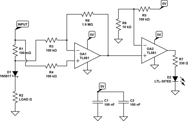
You could put a little 10mΩ or 100mΩ resistor (called a shunt resistor) in series on each power input path before the diode, and use a dual package general purpose op-amp and using two of these, monitor the shunt resistors independently. When some arbitrary current is flowing through the resistor (for example, 200mA) your op-amp will be able to source/sink current through an LED to indicate which input is providing power.

If you had 100mΩ resistor, and 200mA was going through it, the voltage built up across it would be 20mV. You will want to amplify this to make it more reliable and easier for the second stage of the op-amp to act as a comparator. Maybe the output gain of the first op-amp will be 20. This means your comparison voltage for an "ON" condition will be 0.4V.

Your second stage op-amp will then use a voltage divider reference from the 5V rail as the input to the inverting input of the op-amp. 0.4V is basically 1/11th so you can find whatever resistor values work for this, maybe something simple like 10KΩ and 100KΩ (giving you a ratio of 0.091). The non-inverting input is the output stage of the first op-amp, and without feedback the op-amp will act in open-loop (huge gain, basically ON or OFF based on the comparison input).

Finally the output of the second op-amp will go through a resistor and LED for simple indication of the current flowing through the shunt resistor for that particular input. A very simple cheap general purpose op-amp will work for this, and the circuit is very simple. You should be able to find all the parts and prototyping board at your university, and have this all working very quickly.

\$\endgroup\$
8
  • 8
    \$\begingroup\$ As a bonus you could take the output of the op-amps and feed them (via resistor divider to get 3.3V) into two GPIO pins on the Pi so it can know which power source is being used - maybe then turn off some peripherals to save power when running on battery? \$\endgroup\$
    – Majenko
    Commented Sep 26, 2014 at 11:20
  • \$\begingroup\$ indeed, that is a great idea and use of existing circuitry Majenko! \$\endgroup\$
    – KyranF
    Commented Sep 26, 2014 at 11:29
  • 1
    \$\begingroup\$ @SpehroPefhany Perhaps the op amps chosen should be ones that work with 300-500mV above their input rail.. or you mean it literally will not function properly? Is there a way to reduce the sense voltage, perhaps with an input voltage divider on both the inverting and non-inverting inputs? \$\endgroup\$
    – KyranF
    Commented Sep 26, 2014 at 15:11
  • 1
    \$\begingroup\$ It's rare to find an op-amp guaranteed to work in that condition. Maybe use a TSC88 \$\endgroup\$ Commented Sep 26, 2014 at 15:21
  • 1
    \$\begingroup\$ @SpehroPefhany indeed, that one looks fine for the role. two of these acting as OA1 in the schematic and a dual package general purpose or proper comparator op-amp with a shared Vref voltage divider to reduce parts, to switch on/off the LEDs. nice! \$\endgroup\$
    – KyranF
    Commented Sep 26, 2014 at 15:24
1
\$\begingroup\$

Check this circuit using the LTC4412. It does the entire job and provides the "On Battery" indicator.

https://www.analog.com/media/en/reference-design-documentation/design-notes/dn1003f.pdf

\$\endgroup\$
1
1
\$\begingroup\$

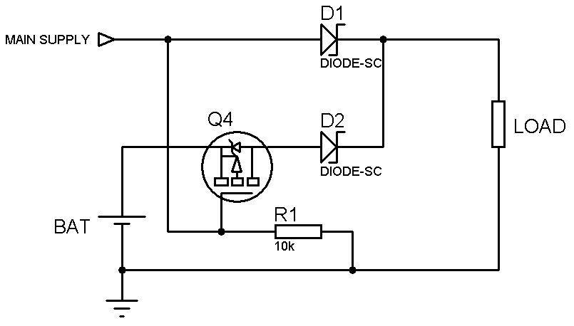
Another solution is the circuit below. It has also been discussed in Stackexchange before.

enter image description here

I'm just not certain what the advantages and disadvantages are when using this circuit compared with the circuit provided by CarpetPython.

Maybe somebody could clarify this?

\$\endgroup\$
2
  • \$\begingroup\$ Well an obvious disadvantage is the diode voltage drop on both, main and battery supply. But that can probably be tolerated for many designs. Other than that it looks nice and simple. \$\endgroup\$
    – Rev
    Commented Jan 21, 2016 at 8:35
  • \$\begingroup\$ actually, this circuit can be improved by: remove D2 and mirror Q4 vertically (switch D and S). The body diode will act like the diode-or when main supply is on so the battery is not back driven. When the main supply is off, Q4 turns on with minimal voltage drop on battery (important to choose a p-fet with low Rds_on when load current is high) \$\endgroup\$ Commented Feb 17, 2017 at 7:46

Your Answer

By clicking “Post Your Answer”, you agree to our terms of service and acknowledge you have read our privacy policy.

Not the answer you're looking for? Browse other questions tagged or ask your own question.