4
\$\begingroup\$

Can someone please explain to me how a passive filter could possibly have a negative insertion loss? In the attached picture, this can be seen in the C or D curves where the insertion loss dips below 0 dB. I understand the filter is resonant at this frequency, but I don't understand how resonance could lead to a negative insertion loss on a passive circuit. This seems to conflict with the fact that passive circuits can't generate power.
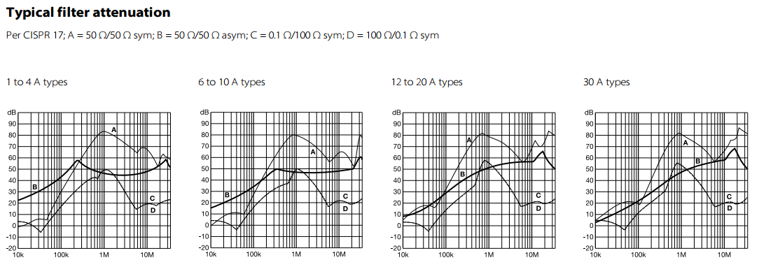
Filter Insertion Loss

\$\endgroup\$

2 Answers 2

2
\$\begingroup\$

Passive circuits cannot produce a power gain but they can produce a voltage gain. A resonant circuit can produce a voltage gain equal to its Q. If the impedance levels are considered, there is no power gain.

\$\endgroup\$
1
  • \$\begingroup\$ Thanks Barry! I didn't realize it was voltage ratio. \$\endgroup\$
    – Awm0121
    Commented Oct 8, 2014 at 16:29
2
\$\begingroup\$

There is a nice white paper from SCHAFFNER explaining the 0.1/100 Ohm curves.

Note that attenuation is measured as a voltage ratio (not a power ratio), so when working at different input/output impedances, you can actually have a voltage gain.

\$\endgroup\$
1
  • \$\begingroup\$ Ah, the clarity...I didn't realize it was a voltage ratio and not power ratio! I knew I was missing something. Thanks for the response! \$\endgroup\$
    – Awm0121
    Commented Oct 8, 2014 at 16:27

Your Answer

By clicking “Post Your Answer”, you agree to our terms of service and acknowledge you have read our privacy policy.

Not the answer you're looking for? Browse other questions tagged or ask your own question.