1
\$\begingroup\$

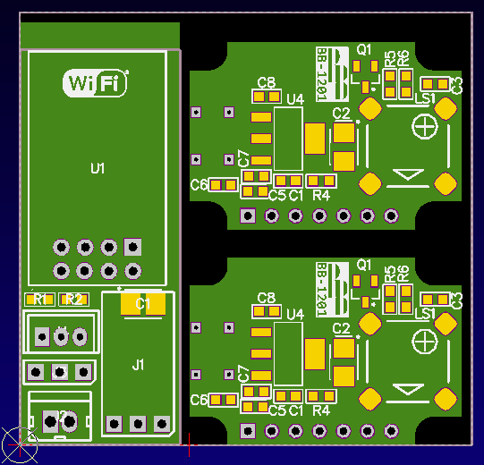
I'm starting my first PCB using Altium and I want to take advantage of small dimensions PCBs cost in order to make my PCB cheaper. As an example take the image below. On the left there's the full PCB and, on the right, I'm splitting it just to make it cheaper (that's not my design, just an example).
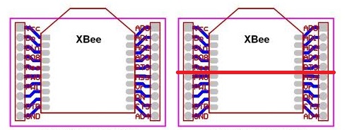
enter image description here

Let's assume that the new PCBs follow manufacturer rules, I'm just wondering if, in order to use those small PCBs discounts, I have to design 4 different schematics.

EDIT Let's take an example. There's a really low price on 10x10 PCBs but yours is 10x20 (which costs 4 times more then a 10x10), but it can be split in half (two 10x10 pcb). Instead of paying the much higer price for the 10x20, I want to able to design a line in Altium and, somehow, make it generate 2 different PCBs.

\$\endgroup\$
6
  • 2
    \$\begingroup\$ Forget about the saving money aspect of doing this for a minute. If you cut a board in half, the only way to get signals from one board to the other is through some sort of connector. That is another couple components to add to the BOM, but more importantly, is another part that can give you trouble in the debugging process. Don't do this. You'll regret it later. \$\endgroup\$
    – Matt Young
    Commented Nov 26, 2014 at 16:42
  • \$\begingroup\$ In this case there is no connectors between them, in this case it's a 2 rows 2mm pitch to 1 row 2.54mm pitch converter \$\endgroup\$
    – rnunes
    Commented Nov 26, 2014 at 16:44
  • \$\begingroup\$ So you want your Altium to split your project into 2 boards and create something equivalent to this, right? link (and it doesnt have to be "sandwich", it might be side by side?) \$\endgroup\$
    – Kamil
    Commented Nov 26, 2014 at 17:19
  • \$\begingroup\$ One of those Xbee adapters is barely 1 inch^2, thats $5 at oshpark. Surely you can spare five bucks to do it right with less risk? \$\endgroup\$ Commented Nov 27, 2014 at 5:20
  • 1
    \$\begingroup\$ @whatsisname that's not my design, just an example \$\endgroup\$
    – rnunes
    Commented Nov 27, 2014 at 12:25

2 Answers 2

2
\$\begingroup\$

Yes.

It's not really clear what you are asking, but the answer is "yes" because Altium can do anything regarding PCB sizes.

Either...

...you mean that you have an existing design and want to "dice" it. In that case, just use cut/paste, as you would in any other software, to move whole sections of layout into a new PCB document.

Or...

...you mean that you have 4 smaller designs in your head and you want to draft them. In that case, create a separate PCB project for each.

Update: Re: Question Edits

From a pure manufacturing basis two 1 unit x 1 unit designs should never be cheaper than one 1 unit x 2 unit design ceteris paribus and assuming they all fit in one panel (which is almost always the case). If you are encountering cost anomalies with your vendor, contact your vendor and negotiate or switch vendors.

That said, there is no built-in functionality to auto-partition a design in the manner you have suggested because there is an insufficient business case for Altium (or any EDA company) to develop such functionality.

Cut-Paste will work fine, but as others have suggested, it's probably best to leave it as one larger PCB.

\$\endgroup\$
1
  • \$\begingroup\$ I edited the question. So, the response it's just cut and paste in new PCB design? \$\endgroup\$
    – rnunes
    Commented Nov 26, 2014 at 16:24
2
\$\begingroup\$

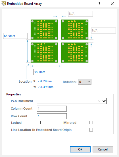
yes, it can be done. In practice what you want to do is embed more board into one outline. All you need to do is to create your PCBs in separate files, and then create a blank one where you have defined your working outline and then you just need to click on the "Embedded Board Array/Panelize" command from the "Place" Menu

Embed board Array

Here you just select the first PCB you want to include, and how many you want. It is pretty self-explanatory. Click OK and place it where you want it. After that, the Embed board will pop up again, where you can pick your second PCB, and continue up to when you are happy with your "mini panel"

Here is a small example I have just put together

Panel Example

Once you're done, just create the gerber files as normal from the panel.

The advantage of doing it this way, is that you keep your PCBs and Schematics separated, as well as you can update each of the designs, and the panel will update as well.

Beware though, The Chinese PCB houses are not too happy when you put more designs into one panel, as they will charge you for each design in that area. There are ways around that, such as making it look like it is all one design, by connecting tracks between the PCBs, but the money you save is not always worth the time.

\$\endgroup\$

Your Answer

By clicking “Post Your Answer”, you agree to our terms of service and acknowledge you have read our privacy policy.

Not the answer you're looking for? Browse other questions tagged or ask your own question.