4
\$\begingroup\$

I'm analysing a PIR Circuit's power supply, but I'm having a large (almost double) discrepancy between simulation/theoretical current values and experimental values (experimental is almost half theoretical)

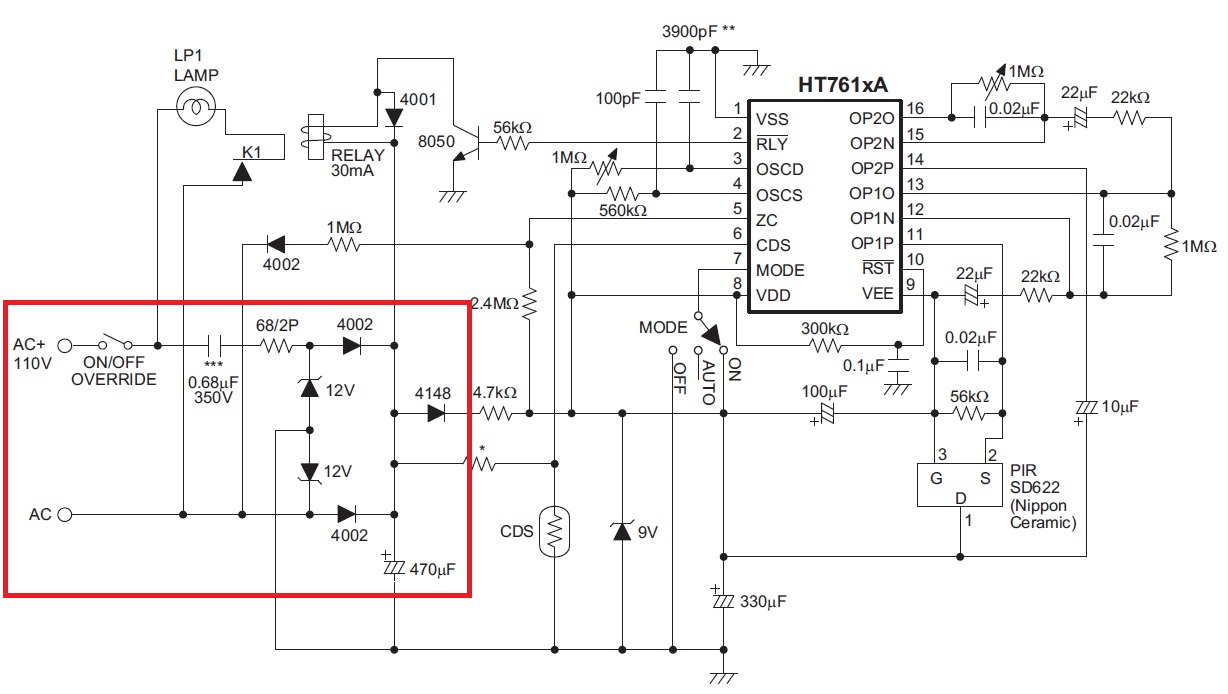
This is a similar circuit to the one implemented in the sensor, however it is 240VAC, the capacitor is 0.39uF, resistor is 150 ohms and the Zener voltage (I'm assuming, given that the voltage at the chip is 9V) ~10V. enter image description here
Here's my simulation circuit of the power supply with no load:
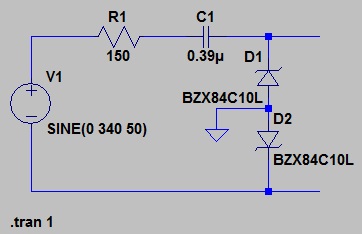
enter image description here

The current through R1 is Irms = 24.3mA, and doing maths gives the same answer. However, when I measure the circuit (when it's on standby, ~100uA current draw from spec sheet), my multimeter says it's drawing 12.75mA, almost half of the theoretical value.

Where have I gone wrong? The capacitor marking is 394, which I'm assuming is 39p * 10^4 i.e. 0.39uF. Further, the meter is a true rms.

Edit:

I calculate a value using:

\$ I = V / Z \$

\$ = (240 - 10) / (150 + 1/(j100*pi*330n)) \$

\$ = 230/(150 - j9645) \$

\$ = 24.8mA < 89.1^o \$

The waveform from the simulation is

enter image description here

\$\endgroup\$
11
  • 2
    \$\begingroup\$ How are you measuring (and calculating) rms current? Is the multimeter a "true rms" one? rms measurements will be quite inaccurate here as the current waveform will not be sinusoidal. I would want to compare simulated and measured waveforms, which would require a scope (and an isolating transformer!) \$\endgroup\$
    – user16324
    Commented Dec 6, 2014 at 12:03
  • \$\begingroup\$ What has the 100uA figure got to do with the circuit? \$\endgroup\$
    – Andy aka
    Commented Dec 6, 2014 at 12:04
  • \$\begingroup\$ @BrianDrummond Added calculations, yes the meter is True RMS. Why isn't the current waveform sinusoidal? \$\endgroup\$
    – tgun926
    Commented Dec 6, 2014 at 12:12
  • 1
    \$\begingroup\$ Unless I'm mistaken your calculation is telling you that the ~25mA is almost purely (capacitive) reactive 'apparent' power draw. So if you find the real part of the 25mA you might be in the order of the 100uA for the 'real' power draw. \$\endgroup\$
    – hooskworks
    Commented Dec 6, 2014 at 12:22
  • 1
    \$\begingroup\$ Why is R1 different? \$\endgroup\$
    – user16222
    Commented Dec 6, 2014 at 12:26

1 Answer 1

1
\$\begingroup\$

The problem is your current measurement method and assumptions for load current.

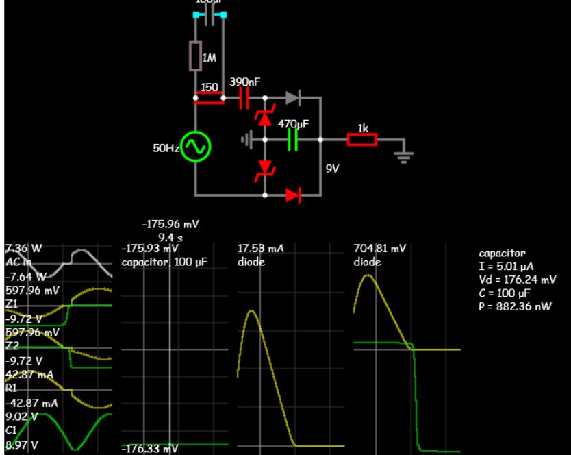
I get I(R1) = 177 mV dc /150 Ω = 1.18mA with a 1K load at 9V out on 470uF cap and 9.7V Zener with Iz=17mA pk using Si diodes.

Since nominal Zener Vz= 9.4~10.6 @ 5mA and Zt is around 15 Ω at 17mA pk

I used 1k load for 1.18mA average. Assumptions for load on mine were different than yours.

Your measurements were:

  • 24.3mA true RMS
  • 12.75mA multimeter

Your assumption on how multimeters work is wrong for AC current.

  • They assume perfect sine wave and measure peak (or average) then scale down by 1/√2 or √2/π (depending on design) to get RMS. But your current is a complex DC + 50Hz AC sine current riding above this. So RMS current is not accurate.

To make accurate complex current measurements with cheap multimeters, use a shunt resistor and 10K R with 100uF cap and measure DC voltage.

enter image description here

My Simulation

\$\endgroup\$

Your Answer

By clicking “Post Your Answer”, you agree to our terms of service and acknowledge you have read our privacy policy.

Not the answer you're looking for? Browse other questions tagged or ask your own question.