0
\$\begingroup\$

This is kind of a follow-up question to Simulation on LTSpice not matching with Calculations at Q-point , which I had asked previously. Here is the circuit again:

enter image description here

The new components added are \$R9=94\Omega\$ and \$C5=1.157\mu F\$. This is intended to reduce the emitter-leg resistance in AC analysis in order to increase AC gain to -50, while keeping DC gain to -10, which was previously the requirement. Here are the full details-

  1. \$V_{in} = 0.6V\$(pk-pk triangular waveform)
  2. \$f=1.17kHz\$
  3. DC gain required = -10
  4. AC gain required = -50
  5. Potentiometer bias = 60k:40k, in order to bring down the swing to 0.6V pk-pk.
  6. Quiescent collector current (Q4) = 1mA

According to calculations, in DC, the capacitor serves as an open circuit, so DC gain is effectively \$-\frac{R5}{R6} = -10\$, neglecting internal emitter resistance. For the AC gain, the capacitor acts as a short, and \$Z_{out}\$ sees a parallel resistance in \$94\Omega\$, so the gain is \$-\frac{4.7k}{470||94}\$ which gives me about -50. The capacitance is set to about \$1.15\mu F\$, keeping in mind the frequency, according to \$\frac{1}{2\pi RC}\$. The problem arises when I simulate the circuit:

enter image description here

enter image description here

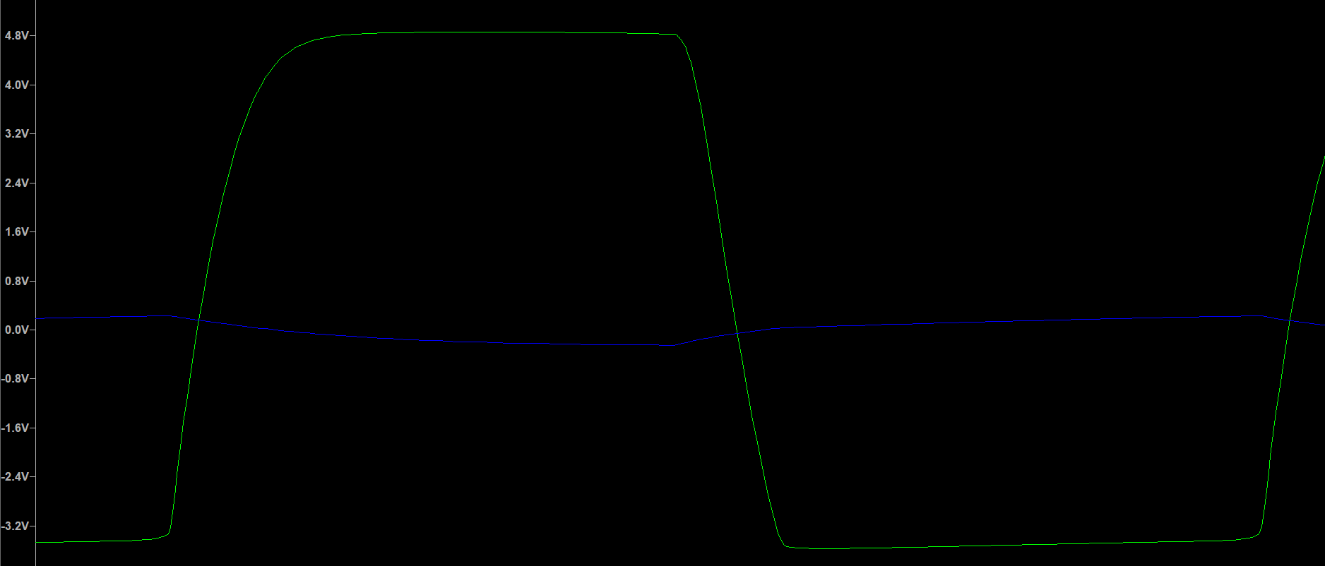
The gain is about -50, as expected, but \$V_{in}\$ falls to an amplitude of 0.2V, instead of 0.3V, which is quite surprising for me. I don't seem to understand this discrepancy. Have I gone wrong somewhere in taking the values for \$R9\$ and \$C5\$? Can someone please explain?

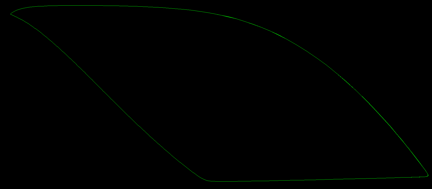
This problem is resolved by changing the capacitor value and making it a high pass filter. When I try to plot the gain in LTSpice, I witness a surprising amount of non-linearity:

enter image description here

I suspect that this is due to the hysteresis caused. How do I reduce this enormous non-linearity in my circuit gain?

PS: I want to add that by changing the potentiometer bias to 30k:70k, I was able to reduce the non-linearity while maintaining the \$V_{in}\$ at a pk-pk of 6V. But I am lacking in clarity currently, changing the potentiometer bias allows a greater input voltage, which is reduced effectively to 0.3V(amplitude), and allows lesser non-linearity. I'm really confused right here. It would be really helpful if someone would help me out.

\$\endgroup\$
7
  • \$\begingroup\$ Tinkering around with R9 and C5, I switched their positions to create a high pass filter, and changed R9 to \$117\Omega\$ and C5 to \$510nF\$. This retained the 0.6V pk-pk input voltage, while maintaining the -50 AC gain. \$\endgroup\$ Commented Sep 8, 2021 at 10:38
  • \$\begingroup\$ It would be really helpful if someone would atleast respond. \$\endgroup\$ Commented Sep 8, 2021 at 15:29
  • \$\begingroup\$ By adding R9 and C5 you have decreased the amplifier input resistance. $$Z_{IN} \approx R_3||R_4||[ (\beta +1) (r_e + (R6||R9)) ]$$ \$\endgroup\$
    – G36
    Commented Sep 8, 2021 at 15:34
  • \$\begingroup\$ That does increase the AC gain, right? But, how to explain this non-linearity and why should I change the potentiometer bias to manage this? \$\endgroup\$ Commented Sep 8, 2021 at 15:39
  • \$\begingroup\$ Nonlinearity on the output waveform? \$\endgroup\$
    – G36
    Commented Sep 8, 2021 at 15:44

1 Answer 1

1
\$\begingroup\$

With an input pk to pk amplitude of 0.6V and a gain of -50 the amplifier is saturating at both its limits which is why the plot shows an almost square wave. So remove R9 and C5 to leave the amplifier with an approximate gain of 10 which should be sufficient. We can adjust the overall gain further using the earlier stage potential divider if required.

If you now make the potential divider 80k & 20k (80k at the top) you should see that the amplifier's output waveform is within its saturation limits but is still a highly non-linear waveform and is more like a capacitor charging curve followed by a capacitor discharging curve. This is because of the RC integrator you are using created from R1 & C1.

Normally an integrator based around an op amp would be used to get a linear ramp up and down. But it is possible to use a simple passive RC integrator if just the lowest section of the capacitor charge/discharge curve is used which gives a more linear ramp up and down than using the whole charge/discharge curve which is what you are attempting to use.

To use just the lowest portion of C1s charge/discharge curve you need to increase the value of R1 to say 47k which will give C1 less chance to charge/discharge on each cycle of the input square wave. By doing this you should find that the amplifier's output is much more linear (closer to the required triangle wave) but it will not be perfect because even the lowest portion of C1's charge/discharge curve has some non-linearity.

By increasing the value of R1 it will have reduced the amplitude of the amplifier's input/output signal but you can increase it again by re-adjusting the potentiometer's resister values and I would start with 50k & 50k and then adjust from there untill the required output amplitude is achieved.

\$\endgroup\$

Your Answer

By clicking “Post Your Answer”, you agree to our terms of service and acknowledge you have read our privacy policy.

Not the answer you're looking for? Browse other questions tagged or ask your own question.