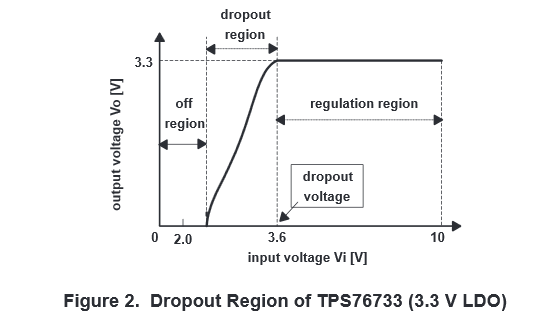
Usually (I can't think of any exceptions) a linear regulator will do its best to maintain the highest output voltage possible, so (above the start-up voltage) the output voltage will track the input voltage with an offset voltage and series resistance (regulators with a MOSFET pass element will only have the series resistance). Both will change a bit as the voltage rises and the MOSFET becomes more enhanced or more base current is available for the BJT.
The startup voltage generally will be poorly defined by the datasheet, but will have to be greater than the threshold voltage or Vbe of the pass element (since regulators use BJTs or enhancement mode MOSFETs). If you're designing your own regulator you could choose to use a depletion mode MOSFET or JFET, in which case it could have a 0V startup voltage, but that's not the norm.
Some regulators provide a "power good" signal that tells you if the output voltage is in regulation (for some definition of that).
If you want different behavior (such as locking out the regulator until the output voltage can be regulated) you can tie a regulator with a shutdown input together with a supervisory chip, but there will generally be some low input voltage where the output is not well defined.
In the case of some bipolar LDO regulators, the current consumed by the regulator may increase greatly as the regulator saturates the pass transistor (which may be a lateral PNP). There was at least one that would draw something like 100mA peak as it passed through the range into regulation. More well-behaved bipolar regulators often list a feature in the datasheet such as "low ground current"- the effect may still be there, but at the tens of mA level.
If you have poor stability in the regulator circuit (mainly an LDO issue), it's also possible for some small amplitude oscillation to occur on the edge of regulation.

