A clever circuit... beautiful and symmetrical (usually, R1 = R2 = R3 = R4 = R) like all the circuits of instrumentation amplifiers... It also gives a good opportunity to show how to make the unfamiliar circuits familiar - by dividing them into more well-known functional blocks instead of blindly analyzing them...
Structure
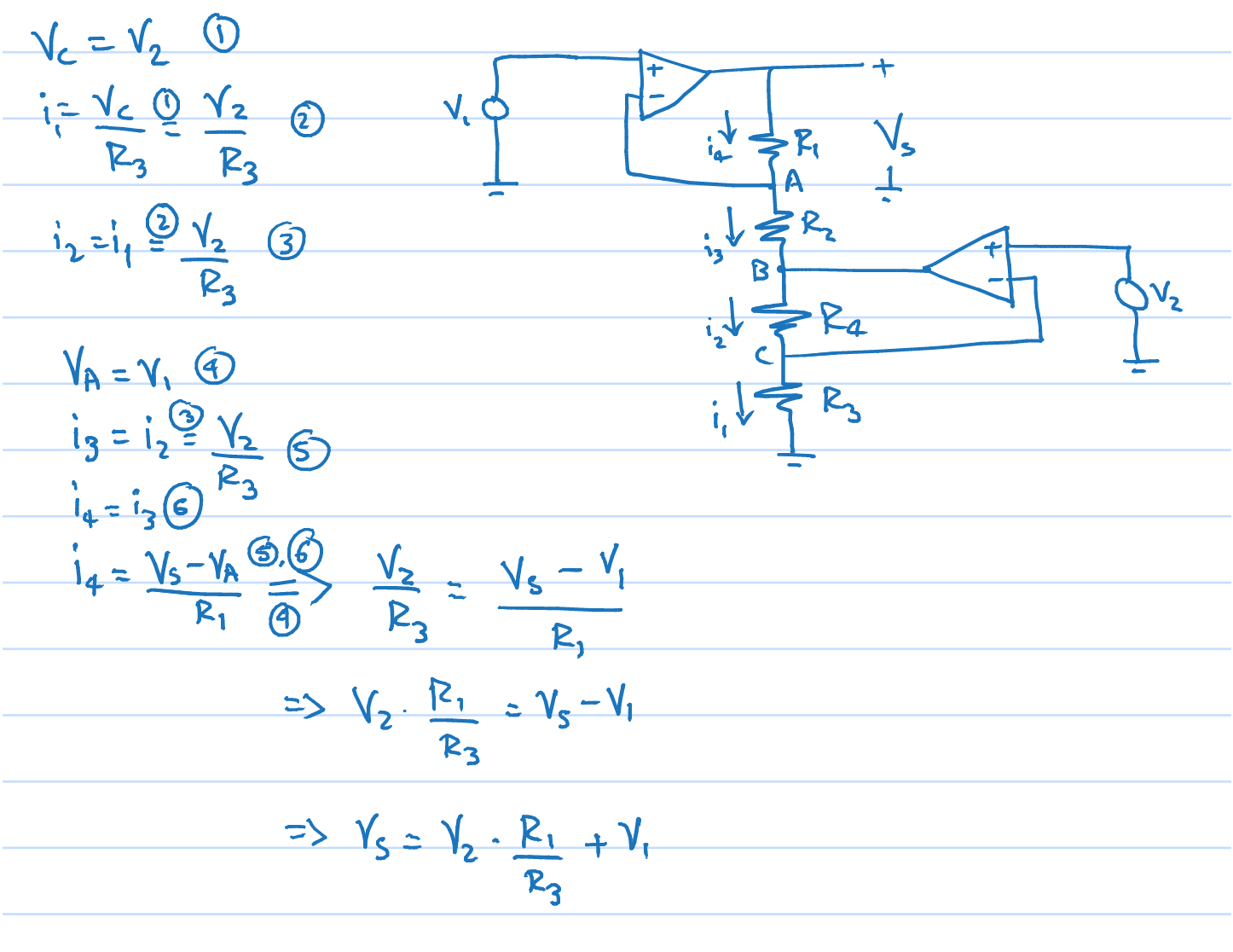
We can discern in this circuit of a perfect instrumentation amplifier two sub-circuits - an imperfect (unbalanced) differential amplifier (the top part consisting of the upper op-amp and the resistors R1, R2), and an ordinary non-inverting amplifier (the bottom part consisting of the lower op-amp and the resistors R3, R4).
Analysis
Let's first consider the upper circuit part. With respect to V1, it is a non-inverting amplifier with gain of 2, and with regard to the lower input (from the side of the lower non-inverting amplifier) - an inverting amplifier with gain of -1. As the lower non-inverting amplifier has a gain of 2, the two gains (inverting and non-inverting) of the imperfect differential amplifier are equalized... the two partial voltages superimpose and mutually neutralize at the op-amp output... and it becomes a perfect balanced differential (instrumentation) amplifier. From this perspective, the analysis is very simple:
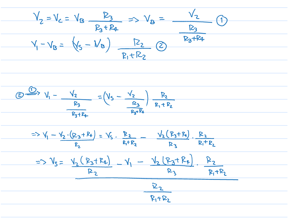
Vs = V1*(R1 + R2)/R2 - V2*(R3 + R4)/R3*R1/R2 = 2V1 - 2V2 = 2(V1 - V2); Happy New Year!
Philosophy
It is interesting to reveal the evolution of the op-amp differential amplifier to see where this circuit solution stays. I will use figurative (not generally accepted) names of the particular circuit solutions that are more meaningful. Also, to simplify this qualitative explanation, I suppose equal resistances (R).
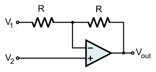
1. Unbalanced "differential amplifier". To make a differential amplifier, we need simply to subtract two input voltages. First we introduce a negative feedback by two resistors to obtain a fixed stable gain and then apply the two voltages to the inverting and non-inverting inputs of this "differential amplifier". Here the low resistance of the inverting input is a problem... but the big problem is that the two gains are not equal - the inverting gain (1) is less than the non-inverting gain (2). So, we have two choices to equalize them - to decrease (two times) the non-inverting gain or to increase (two times) the inverting gain. Let's consider them below...
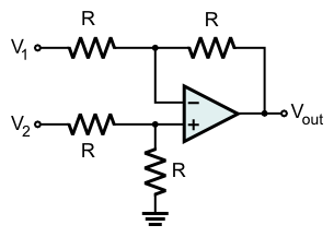
2. Differential amplifier with non-inverting attenuation. To decrease (two times) the non-inverting gain, we can connect a voltage divider (with two equal resistors) before the non-inverting input thus obtaining the classical 1-op-amp differential amplifier. The two gains are now equalized... but the high resistance of the non-inverting input is decreased...
3. Differential amplifier with inverting amplification. With the same success we can increase (two times) the inverting gain if we connect a non-inverting amplifier (with a gain of 2) before the inverting input (the discused here solution). The two gains are equalized again... and the both inputs have high resistance... It is a real 2-op-amp instrumentation amplifier.

4. Buffered differential amplifier with non-inverting attenuation. Finally, we can modify the classic 1-op-amp differential amplifier (case 2) by including non-inverting amplifiers before its inputs; this will solve the problems of the low input resistances. But another problem is that they will ampliify both differential and common-mode input voltages.
5. Buffered differential amplifier with interconnected non-inverting amplifiers. If we are inventive enough, we will combain the two lower resistors of the voltage dividers (inside the input non-inverting amplifiers) into one resistor (Rgain) that can regulate simultaneosly both the input gains. Thus we will obtain the classic 3-op-amp instrumentation amplifier.
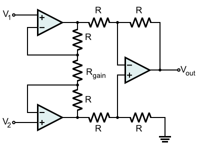
It is interesting that (only) in differential mode, there is a virtual ground in the middle point of Rgain; it has replaced the real ground. As a result, the common-mode input voltages are not amplified (k = 1); only the differential input voltage is amplified.
What is the OP's circuit?
The answer is obvious:
It is a "differential amplifier with inverting amplification" (number 3 above).
Generalization
Finally, let's generalize these techniques in a rule:
If a differential circuit is unbalanced, you have two options - to connect
- an amplifier to the input with the lower gain or
- an attenuator to the input with the higher gain.
See also
What is the idea behind the op-amp instrumentation amplifier? (my Codidact paper)
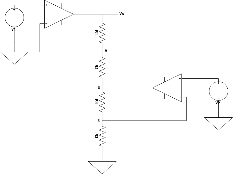

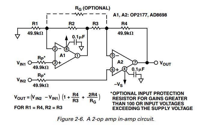 -- though the resistor numbers and inputs are not quite the same as what you use


i3=i2at node B, but you neglect the current from the output of the lower op-amp, which is not negligible in general. \$\endgroup\$