2
\$\begingroup\$

I have this question but I am really confused about how to start, can you please give me some helpful hints.

Let us assume we have a DC voltage measured in a circuit, called \$V_{\text{in}}\$. We intend to build a circuit such that it has a transfer function defined as

$$H(s) = \frac{V_{\text{out}}(s)}{V_{\text{in}}(s)} = \frac{s^2+s+1}{s}$$

Draw this electrical circuit. The circuit can be composed of resistors, inductors, capacitors and op amps only.

I tried op amps with resistors and capacitors in a few different forms, but I didn't get the same \$H(s)\$.

Also I tried a few filters but non of them gave me the same answers.

\$\endgroup\$

4 Answers 4

3
\$\begingroup\$

\$\dfrac{V_{OUT}}{V_{IN}}\$ = \$\dfrac{s^2 + s + 1}{s}\$

Divide thru by s to get \$s+1+\dfrac{1}{s}\$

Now you have three terms that are summed together and one of them is based around a resistor, one a capacitor and one an inductor. Does this help? I'm not going to do the full job because it sounds like homework.

Can you take it from here?

\$\endgroup\$
2
  • \$\begingroup\$ At start I simplified first and I knew I can have resistor and capacitor and inductor but I don't know in what order should I connect them together when I want to draw them in Pspice.is there any chance that we can find what kind of filter this circuit can be? \$\endgroup\$
    – Mona
    Commented May 28, 2014 at 13:23
  • \$\begingroup\$ Treat them as three op-amp separate blocks then sum the outputs in a fourth op-amp block. The three separate blocks are all fed with Vin and the three outputs go into a fourth op-amp used as a summer. Does this make sense? Then if you need to, simplify but I don't think there's much to simplify. \$\endgroup\$
    – Andy aka
    Commented May 28, 2014 at 13:36
0
\$\begingroup\$

First thing- since the vin is DC, s=0 and H(0)=infinity, Second- for the case where both input and output are voltages, the degree of the numerator can't exceed the degree of the denominator which is being violated here, so it's impossible to build the circuit in real world.

\$\endgroup\$
4
  • \$\begingroup\$ Perhaps in its non-reduced form. See Andy's simplification. \$\endgroup\$
    – sherrellbc
    Commented May 28, 2014 at 13:43
  • \$\begingroup\$ what andy is saying would be right if input was a current and the transfer function an impedance, then you could make a series RLC circuit out of the simplification but this is not the case here. \$\endgroup\$ Commented May 28, 2014 at 13:49
  • \$\begingroup\$ @SalmanAzmat It's a three term controller (PID controller) - can you not see that? \$\endgroup\$
    – Andy aka
    Commented May 28, 2014 at 14:03
  • \$\begingroup\$ Oh yeah, just read again and realized that op-amps are also allowed,, but still for DC input integral's gonna give infinite output(ideally) or saturate the op-amp in this case, \$\endgroup\$ Commented May 28, 2014 at 14:12
0
\$\begingroup\$

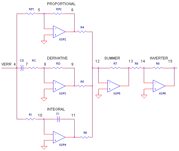
enter image description hereCan you please verify that this circuit is what the posts are about?
\$\endgroup\$
4
  • 3
    \$\begingroup\$ We're trying to help the OP by not feeding the answer directly. Has all subtlety been lost from the modern world? BTW your circuit is nearly right except for one glaring mistake. I also won't pull you up on the RC resistor in series with CD - this is a theoretical exercise and it isn't needed. \$\endgroup\$
    – Andy aka
    Commented May 28, 2014 at 13:50
  • \$\begingroup\$ @Andy, what is the purpose of RC in a real-world application? \$\endgroup\$
    – sherrellbc
    Commented May 28, 2014 at 13:59
  • \$\begingroup\$ @sherrellbc it's there to limit the gain of that particular op-amp and prevent it trying to close the loop against a signal that has very high rate of change. Same with a real world integrator - it would normally have a high resistance resistor in parallel with the feedback capacitor. \$\endgroup\$
    – Andy aka
    Commented May 28, 2014 at 14:05
  • \$\begingroup\$ I see the logic in the case of the integrator (there always exists a feedback path with the parallel resistor), but how does a resistor in series with CD prevent losing the feedback path? If Dv/Dt were really high then the impedance of the capacitor would be negligible and the amplifier would simplify to just the input with a resistance in the feedback loop. Would it be that the gain would rail otherwise (it now looks like an inverting amplifier with 0 resistance at the input -> Vo = Vi*(Rf/0))and RC provides a way to limit this maximum gain? \$\endgroup\$
    – sherrellbc
    Commented May 28, 2014 at 14:09
0
\$\begingroup\$

This is a improper transfer function: The system has more zeros than poles; it is not causal, cannot be implemented, has a strictly proper inverse and has infinite high-frequency gain.

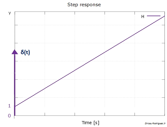
$$\frac{Y(s)}{X(s)}=H(s)=\frac{s^2+s+1}{s}$$ with impulse response: $$y_i(t)=\delta(t)' + \delta(t) + u(t)$$ with step response (also with a discontinuity in origin): $$Y_s(s)=1+\frac{s+1}{s^2}$$ or, in time: $$y_s(t)=\delta(t) + u(t)+ t$$

Figure 1

Improper Additional comment on realizable x unrealizable TFs:
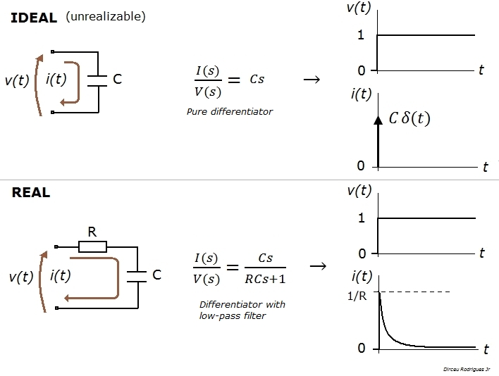
Figure 2

Improper2 UPDATE:

Seen as a PID controller,

$$H(s)=\frac{s^2+s+1}{s}$$ has the form

$$\frac{K_Ds^2+K_Ps+K_I}{s}=K_p(1+\frac{1}{T_Is}+T_Ds)$$

Clearly, this transfer function is improper and practically it can not be used as frequency increases, its gain also increases In consequence, practical applications apply a low-pass filter in the D-term, of the form \$1/(T_fs+1)\$. This low-pass filter has the effect of attenuating high-frequency signals. What lead us to a practical PID controller:

$$H(s)=K_p(1+\frac{1}{T_Is}+\frac{T_Ds}{T_fs+1})$$

Note that, for the modified D-term, the high frequency gain is given by \$\frac{T_d}{T_f}\$ (where \$T_d > T_f\$), instead of \$\infty\$, for the pure differentiator \$T_ds\$. Compare with Figure 2 above (ideal x real).

\$\endgroup\$
1
  • \$\begingroup\$ Would "s" be considered an improper transfer function? What about "1/s"? \$\endgroup\$
    – Andy aka
    Commented May 28, 2014 at 18:44

Your Answer

By clicking “Post Your Answer”, you agree to our terms of service and acknowledge you have read our privacy policy.

Not the answer you're looking for? Browse other questions tagged or ask your own question.