12
\$\begingroup\$

schematic

simulate this circuit – Schematic created using CircuitLab

OK. So I've been told that the current flowing into the current source (that is, into the arrow's behind) is the same as the current coming out of the current source (that is, out of the arrow's head).

If this is the case, then why is it a current "source"? It's not providing any extra current!

I know this is a fairly elementary question, but I haven't found a good answer elsewhere.

Thanks.

\$\endgroup\$
2
  • \$\begingroup\$ It's implicit in the symbol, but explicitly it's a "constant current" source. \$\endgroup\$
    – EM Fields
    Commented Jan 22, 2015 at 1:03
  • \$\begingroup\$ Think about the water analogy. It's like you've installed a pump which causes a constant amount of water to flow through it. The water input to the pump equals the water output to the pump. And yet it's providing the flow, hence the "source". \$\endgroup\$ Commented Jan 23, 2015 at 3:19

8 Answers 8

24
\$\begingroup\$

The current in any 2 terminal device is always the same, there's no way for a 2 terminal device to provide "extra" current. You can't have 0A in and 4A out.

What it does do is force the current to be the given value regardless of the impedance across it. (So therefore you can't put in an open circuit an ideal current source, the voltage would go to infinity.)

So a resistor by itself has no current through it. Hook it across an ideal current source and you get (for your example current source) 1A through it regardless of the value of the resistor.

\$\endgroup\$
16
\$\begingroup\$

A current source is a voltage source which - in ideal circumstances - creates as much voltage as needed for the specified current to flow. Think of it as a power supply with an adjustable voltage and a fairy watching the current and adjusting the voltage rapidly to preserve the constant current.

An ideal current source would suppply the required voltage in any case, so one with open terminals would output millions of Volts to create an arc through the air - of course this very rarely happens with real current sources.

A current source is not a single circuit element, but a close enough approximation can be made out of ordinary circuit elements. Such current sources are often used to drive LEDs and lasers where little differences in the voltage would lead to dim or burnt-out LEDs, but a current limiting resistor dissipating half the power would also not be acceptable.

Current sources also can be thought of as an opposite of ideal batteries, a.k.a. voltage sources. An ideal voltage source keeps the voltage constant across its terminals; a current source keeps the current constant across its terminals the current flowing through itself constant.

Voltage sources "like" their terminals open - no current flows then, no energy is output. They "hate" being short-circuited - that results in infinite current and molten wires at the least.

On the contrary, current sources "like" their terminals shorted. Then only a tiny voltage is required to drive the specified current. But they "hate" being left open; they put out enormous voltages to try to push the current through.

\$\endgroup\$
2
  • 2
    \$\begingroup\$ You might want to change your 4th paragraph. Voltage is across the terminals of a device, but current flows thru the device. I think it's wrong to say "current across its terminals". But +1 anyway for a intuitive description. \$\endgroup\$ Commented Jan 22, 2015 at 15:14
  • \$\begingroup\$ Thanks, I fixed it. As a non-native speaker these nuances sometimes evade my sight. \$\endgroup\$
    – matega
    Commented Jan 22, 2015 at 17:25
3
\$\begingroup\$

Well....it is a source in the sense that it will work to keep the current in it's circuit loop constant. The voltage across the source will adjust to what is necessary in the circuit to allow the constant current to flow.

\$\endgroup\$
2
\$\begingroup\$

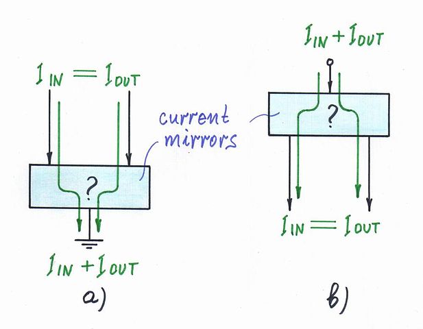
Nice question, David... It is sooner about the nature of a current amplifier - current-controlled current source (CCCS) or a magnifying current mirror, than the simple 2-terminal current source.

So it is possible to obtain an output current bigger than the input current but only if there is a third terminal (as in the current sinks and sources in the picture below). In each of these configurations, there are two particular current loops while in your configuration of a an ordinary 2-terminal loop there is only one common loop. See this Wikibooks story about the basic idea behind the simple current mirror.

Current mirror - topology

Ordinary 2-terminal (1-port) electrical sources actually are 2-port devices. Their input ports are nonelectrical, and the output ports are electrical (producing current or voltage). The output quantity of a current source is a kind of a flow-like quantity (electrical flow or current) "moving" along the loop... and, of course, the flow is the same along the common loop. The output quantity of a voltage source is a kind of a pressure-like quantity (electrical "pressure" or voltage) applied across all the loads connected in parallel to the voltage source... and, of course, the pressure is the same across the common load terminals...

\$\endgroup\$
2
\$\begingroup\$

A current source regulates the current that flows through itself by adjusting the voltage across itself. Regulating a current may mean creating it if it does not exist (which is why current sources are not meant to be in an open circuit as they will try to force one by increasing their voltage until it is maxed out or it breaks through air). It is normal that the same current goes in and out, since the current goes through it - the source is in series with that branch of the circuit.

Current sources can be used to create a current, or to ensure the current in that branch of the circuit is at a known value. When you think about it, a simple resistor with a voltage source can be a current source - a not particularly efficient or compliant/robust one but it still is. If a current source is used to create a current, this current can be injected in other branches as currents add up at each circuit node.

Voltage is generally used to transport information, but current sources are everywhere. From biasing to driving LEDs.

\$\endgroup\$
1
\$\begingroup\$

It is the symmetry of voltage source. Ideally it has infinite impedance, whereas voltage source has zero. (Impedance of en element is the ratio of voltage change over current change on it in the same step.) In the parallel universe of current source kingdom, the battery's current is constant and on storage its poles are short circuited. That is how it stays on zero power level. Having constant current without any voltage pressure won't sacrifice any energy, it is the inertia of the electron movement. Of course on practice there would be some resistance of the wire, some energy would have been spend to companse the the tendency to slowdown of movement, a small amount of voltage would be generated. Likewise the normal battery, the leaking current over the air.

The constant current source can be realized with active components (transistors). You may need it to deal with very low impedance components easier because of its symmetry. Think about the LEDs. With c.v.s., to maintain the constant power, you need a current limiting resistor. With c.c.s., voltage is being due to the nature of particular LED, no need for any extra component, so the power is controlled with just one parameter.

Indeed, the current source exists in nature somehow. But not constant near anywhere the battery can does, so you see it as a variable function of something. If you examine the current in a coil, you can see that for infinitesimal slices of time, it acts as a different value of constant current source for every time slice, thus being a function of time, because of its very limited energy capacity.

\$\endgroup\$
1
\$\begingroup\$

In terms of what a constant-current source does, one old traditional use was for carbon-mike style "intercoms" such as was once used by TV camera operators to communicate with the control room. Basically, there would be a single pair of wires running to all the cameras, and to the control room positions, parallel wired. The operators (both camera and control room) would plug in with a headset containing carbon mike and dynamic (electromagnetic) earphone, wired in parallel. Some setups incorporated a small transformer at each station so that the mike current would "buck" the headphone current for that station.

The wire pair would be connected (in the control room) to something resembling a constant-current source. Older versions were a large battery and a resistor, or, if a little fancier, a large inductor. But this was replaced, when they became available, with a crude constant-current supply (which provided much better sound).

This setup worked quite niftily (especially with the constant-current supply). Anyone speaking in one mike could be heard by everyone, and headsets (within reason) could be plugged and unplugged without seriously upsetting the "balance" of the system. And it only required a single pair of wires.

\$\endgroup\$
0
\$\begingroup\$

I understand the confusion on the subject, when elect engr students are introduced to ideal current sources. We are surrounded in real life by voltage sources ... we buy batteries with rated voltage. The power supply to our homes is a virtually ideal voltage source, in that multiple devices (loads) are placed on the power grid, but voltage remains constant. The water pressure to your house is similar to an ideal voltage (electrical pressure) source, so that users down the street don’t affect your pressure. When you have a fully charged car battery, you know that if you dead short the terminals (almost zero resistance), you get a violent reaction (not infinite current, but a buttload!). If you had an ideal current source sitting on a bench top open-circuited, you would see lighting arcing between the terminals, because the constant current device would have to overcome the very high resistance of air by having a potential of thousands of volts. Seems like that would be dangerous.

I tend to think of pressure driving flow in natural systems. So, electrical pressure, measured in volts, driving current, measured in amperes, through a circuit. Voltage is the independent variable, and current is dependent variable.

For purposes of circuit analysis, you need ideal voltage and current sources to do Norton and Thevenin equivalents… very handy. And you can build a constant-current source with a transistor and a few resistors, or an op amp & mosfet that works as advertised within a given range.

\$\endgroup\$
2
  • \$\begingroup\$ Welcome to EE.SE. It is not entirely wrong or uninteresting what you wrote. However it doesn't answer the question. Please try to stick to the question when writing answers. \$\endgroup\$
    – Ariser
    Commented Apr 5, 2020 at 5:39
  • \$\begingroup\$ Yes, I understand that I strayed into peripheral areas, but the question "What's the point of a current source?" highlights the fact that it seems like a strange thing, and we don't see good examples or analogs in nature. Short answer of course is that a current source provides a constant current through a circuit regardless of load by adjusting voltage - within a range. \$\endgroup\$
    – user248150
    Commented Apr 6, 2020 at 21:03

Your Answer

By clicking “Post Your Answer”, you agree to our terms of service and acknowledge you have read our privacy policy.

Not the answer you're looking for? Browse other questions tagged or ask your own question.