2
\$\begingroup\$

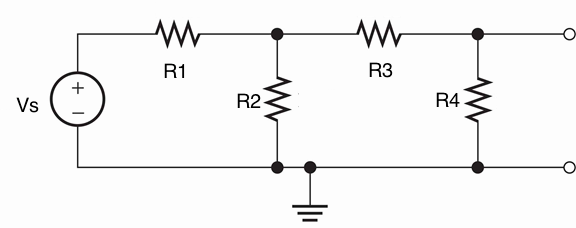
In the circuit below, Vs=18V, R1=100Ω, R2=100Ω, R3=100Ω, and R4=100Ω.! Determine RTh for the Thévenin equivalent circuit.
enter image description here

I know to find the thevenin resistance, all independent voltage sources are converted to shorts and current sources are converted to open circuits.

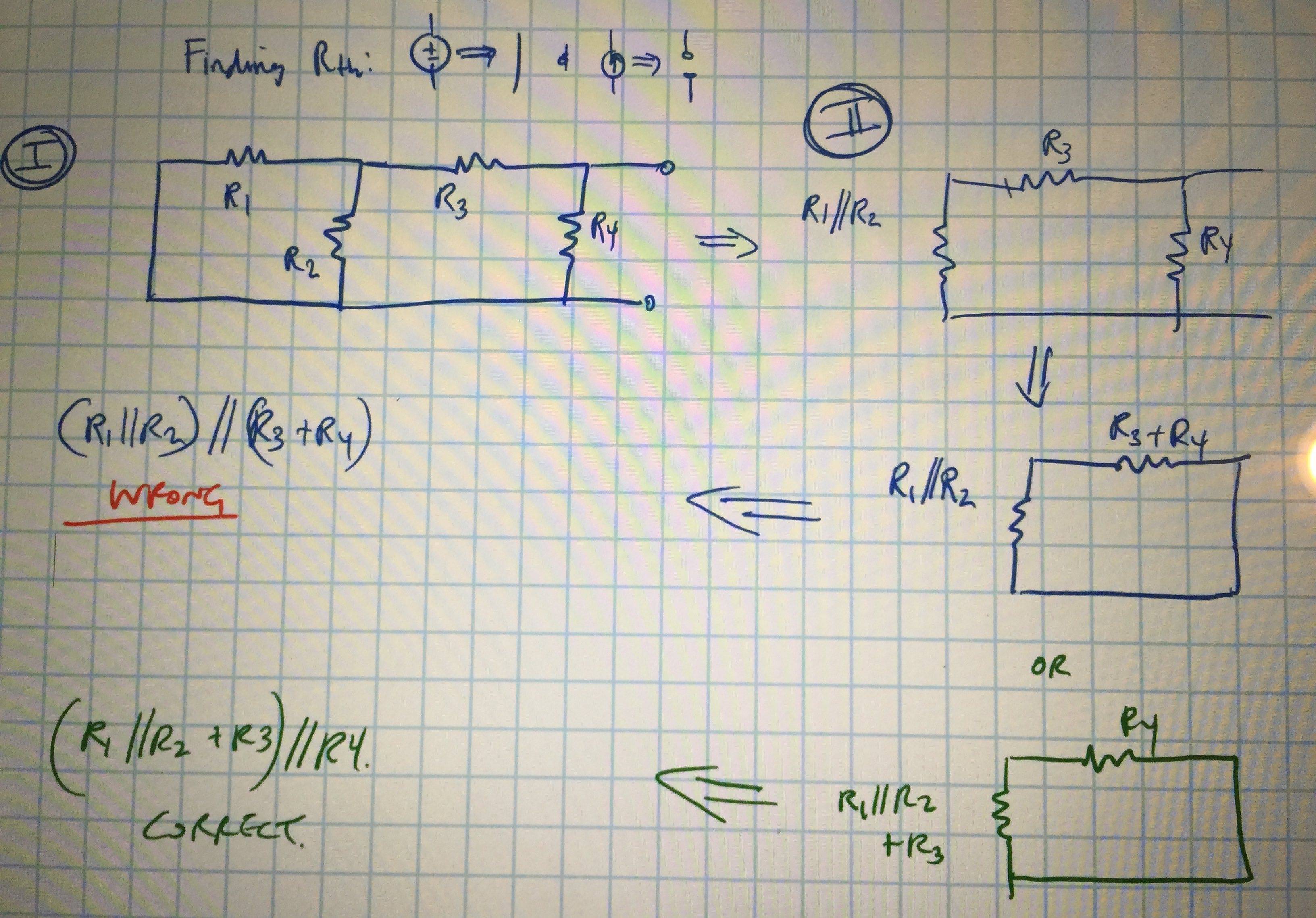
In the diagram above, if the circuit is if the voltage source is replaced with a short, then R1 // R2. My confusion is in part II of the diagram. I thought in part II of the simplified circuit, it doesn't matter how the final circuit is decomposed--but apparently it does. When I simply for the circuit as I did in green, I get the correct solution, but in the the blue ink, its incorrect... why?

In part II, I thought R3 and R4 are in series and (R1//R2) is in series with R3. Why is (R1//R2) //(R3+R4) incorrect?
enter image description here

\$\endgroup\$

2 Answers 2

1
\$\begingroup\$

You can't consider R3 and R4 in series because of the terminal there on the node between R3 and R4. In order to be in series, the components have to have the same current path. With no load connected between the terminals, they would be in series, but that rather defeats the purpose of a source. So the correct Req would be ((R1 // R2) + R3) // R4.

\$\endgroup\$
3
  • \$\begingroup\$ Thanks... So when calculating the thevenin resistance, you have to assume that there "would" be a load there even though it's shown without one to do the calculations. Right? \$\endgroup\$ Commented Jan 22, 2015 at 6:45
  • \$\begingroup\$ The idea is you can do all of this work once to figure out what happens when you connect ANY load that would be connected across those terminals, without having to re-analyze the circuit with a specific load connected. \$\endgroup\$ Commented Jan 22, 2015 at 8:27
  • \$\begingroup\$ In general when there is an 'external' terminal in a circuit, you cannot optimize away the node that it is connected to as you will just be shooting yourself in the foot. \$\endgroup\$ Commented Jan 22, 2015 at 8:29
0
\$\begingroup\$

Perhaps a visual breakdown of the steps might clarify the procedure.

enter image description here

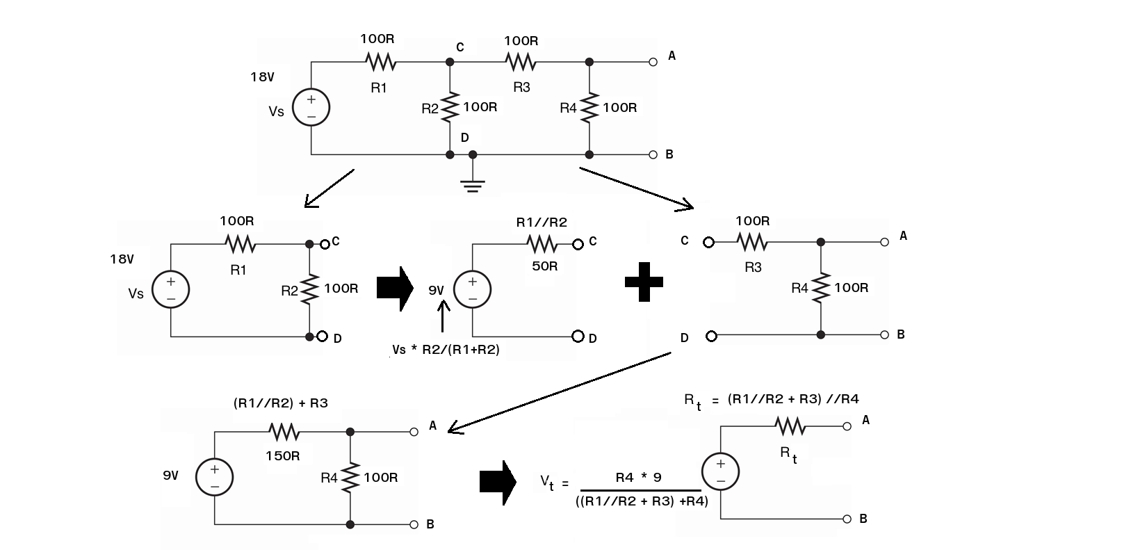
Split the circuit at points C D and convert the left hand part of the circuit to a Thevenin equivalent. Its Thevenin voltage will be 18* R2/(R1+R2) ( = 9V ie the open circuit voltage across C D). As R1 = R2 this will be 9V. The Thevenin resistance for this circuit will be R1 in parallel with R2 (R1//R2) or 50 ohms.

You can easily determine this value by putting a short circuit across C D and use Ohms law to calculate what equivalent series resistance would produce the short circuit current from a 9V source (18/R1 = 9/R)

Now add the second part of the circuit to the Thevenin equivalent of the first part of the circuit and simplify. (R1//R2 + R3) becomes the single value resistance from the first Thevenin voltage (9V).

What should be obvious now is that the Thevenin equivalent resistance of the circuit is (R1//R2 + R3) // R4 and the the Thevenin equivalent voltage will be 9 * R4 / ((R1//R2 +R3) + R4)

\$\endgroup\$

Your Answer

By clicking “Post Your Answer”, you agree to our terms of service and acknowledge you have read our privacy policy.

Not the answer you're looking for? Browse other questions tagged or ask your own question.