6
\$\begingroup\$

I have two PIC18F4620 connected via SPI + Slave Select + additional IRQ line. Both controllers are driven from the same crystal oscillator using the same clock settings. The master sends one byte and then waits until the slave toggles that additional IRQ line. The duration of the toggling is 4 instruction cycles. All the edges look good on the scope and SPI communication works properly, except for the detection of the toggling (while(!PORTBbits.RB1);).

This is my SPI sending code:

    while (spi_out_msg_buffer.write_cursor > spi_out_msg_buffer.read_cursor)
    {
        DisableInterrupts;
        SSPBUF = spi_out_msg_buffer.data[spi_out_msg_buffer.read_cursor];
        LATBbits.LATB0 = 1;
        while(!PORTBbits.RB1); // wait for toggle on IRQ line
        LATBbits.LATB0 = 0;
        EnableInterrupts;
        spi_out_msg_buffer.read_cursor++;
    }

The while(!PORTBbits.RB1); is translated into two instructions:

BTFSS PORTB, 1, ACCESS
BRA 0x188

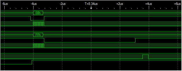
I insterted that B0 line for debugging purposes, you can see it at the very bottom of this timing diagram:
timing

You can see the toggling of the IRQ line (second from the bottom) and how it goes undetected, because the B0 debugging line stays high. When I stop the execution via ICD it hangs inside the while. It is worth to mention that it usually works for a few bytes and then stops, as you can see here:
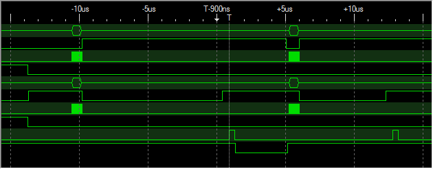
whole timing

I measured that the pulse is actually 4 instruction cycles (= 16 PLL cycles = 4 clock cycles) long:
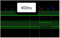
pulse length

I think that should be sufficient for the pulse to be detected. Even if the first BTFSS misses it because the port is sampled at the beginning of the instruction cycle, then the second one should get it:

even more timing

10 MHz -> PLL -> 40 MHz -> 10 M instructions per second -> 100 ns per instruction.

Shouldn't that be long enough to exit the while?

\$\endgroup\$
2
  • \$\begingroup\$ check your assembly code, it could easily be more then 4 instructions, although in this case it could be less. \$\endgroup\$
    – Kortuk
    Commented Jul 5, 2011 at 6:09
  • 1
    \$\begingroup\$ Why not use the level-change facility of a number of the PIC's IO lines? This updates a flag (and/or triggers an interrupt) when the value on the pin changes. This in independent of the instruction clock and should make your system more reliable. \$\endgroup\$
    – Majenko
    Commented Jul 5, 2011 at 9:46

3 Answers 3

6
\$\begingroup\$

You're using a compiler, so you have no idea how many cycles that polling loop takes. In assembler you could get it down to 3 cycles, but you gave up the right to count cycles when you wrote the code in a high level language.

However, the real problem is the overall approach. Asking the code to catch a short glitch is not a good idea. Even if you could guarantee the loop time is less than the glitch time, you can now not turn on interrupts during the wait. This may present architectural problems later.

A much better idea is to use the hardware you already have to catch the glitch, then have the firmware check that hardware. The simplest would be to wire the glitch into one of the INTx lines, then look for the INTxIF flag. Change detect pins would also work, but keep in mind the flag gets set on both edges and you have to clear the mismatch to clear the condition.

\$\endgroup\$
4
  • \$\begingroup\$ You can still count cycles when you're using a high-level language, it just takes some digging. I agree, though, using hardware would be a better way overall. \$\endgroup\$ Commented Jul 5, 2011 at 13:41
  • 2
    \$\begingroup\$ @Kevin: You can count cycles with some digging, but the answer isn't very meaningful. It will tell you only what that version of the compiler at that optimization setting and other possibly non-obvious parameters does. If you need to guarantee the number of cycles in a loop, you have to disable interrupts and write it in assembler. \$\endgroup\$ Commented Jul 5, 2011 at 14:12
  • \$\begingroup\$ I disabled interrupts as you can see in the code and I copied the assembly snippet in the question right from the disassembly, so that is exactly what gets executed on the PIC, isn't it? \$\endgroup\$
    – AndreKR
    Commented Jul 5, 2011 at 14:23
  • \$\begingroup\$ I already deliberately used pin B1 for the IRQ line, so indeed I can take advantage of its interrupt capability. However, I am very curious why it doesn't work this way. \$\endgroup\$
    – AndreKR
    Commented Jul 5, 2011 at 14:30
5
\$\begingroup\$

The last instruction it's an unconditional branch, right? Usually branches and memory accesses (made on the first instruction, right?) take about 2-3x more time to execute, so in you're case those instructions could take about 16 cycles to execute, which is 400ns (on the best case scenario).

\$\endgroup\$
9
  • \$\begingroup\$ Can you give more information about how the OP(original poster) might go about finding this out. How can you get around this? Lets solve a problem! I pointed out in my comment they should check their assembly code. \$\endgroup\$
    – Kortuk
    Commented Jul 5, 2011 at 9:19
  • \$\begingroup\$ I'm not a PIC18 expert, but according to this site you have a flag that's updated when the SPI send/receive operation ends. Try replacing that line for while(!SSPSTATbits.BF);. \$\endgroup\$
    – rnunes
    Commented Jul 5, 2011 at 12:56
  • \$\begingroup\$ Oh, indeed I was unaware of the fact that the BRA takes two instruction cycles, but still 400 ns should be sufficient, or not? I updated the question with how I imagine the worst case. \$\endgroup\$
    – AndreKR
    Commented Jul 5, 2011 at 14:21
  • \$\begingroup\$ @AndreKR: PORTB it's an address right? If it is then BRFSS will probably take the same time as the branch to complete (because the MCU have to load the value on PORTB to a register). Why don't you try my suggestion on the comment above, wich I believe it's the same of @MattJenkins on the first answer? \$\endgroup\$
    – rnunes
    Commented Jul 5, 2011 at 15:06
  • \$\begingroup\$ From the datasheet: All single-word instructions are executed in a single instruction cycle, unless a conditional test is true or the program counter is changed as a result of the instruction. In these cases, the execution takes two instruction cycles, with the additional instruction cycle(s) executed as a NOP. Your suggestion has nothing to do with my problem. MattJenkins' is the same as Olin's suggestion, please see my comment there. \$\endgroup\$
    – AndreKR
    Commented Jul 5, 2011 at 16:47
2
\$\begingroup\$

The actual reason was me being a moron. My DisableInterrupts macro did INTCONbits.GIE=1.

I found this by toggling a pin during busy waiting:

while(!PORTBbits.RB1)
{
    LATBbits.LATB0 = 0;
    LATBbits.LATB0 = 1;
}

I noticed that the toggling stopped in regular intervals and when the notification pulse falls into one of these windows, it goes unnoticed.

enter image description here

\$\endgroup\$
1
  • \$\begingroup\$ None of you could know that, nevertheless +1 for both your answers for pointing me to the cycle count and the pinchange interrupt. \$\endgroup\$
    – AndreKR
    Commented Jul 10, 2011 at 2:42

Your Answer

By clicking “Post Your Answer”, you agree to our terms of service and acknowledge you have read our privacy policy.

Not the answer you're looking for? Browse other questions tagged or ask your own question.