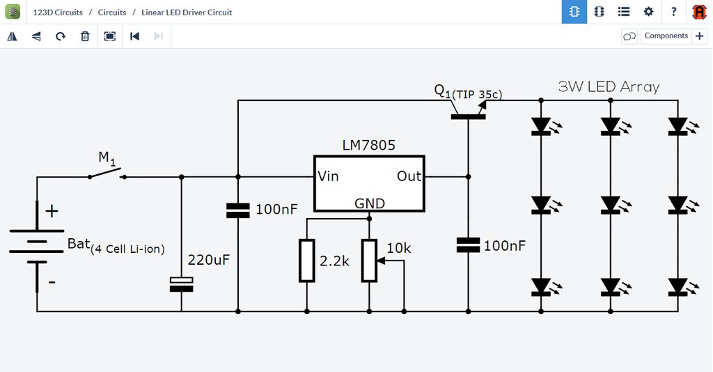
This is an LED driver circuit, but what is the use of the transistor in it?

This is an LED driver circuit, but what is the use of the transistor in it?
The 7805 regulator is setup as an adjustable regulator as adjusted by the 10K pot. The transistor is connected as an emitter follower to increase the load current available to the LED load. Supposedly the 7805 is not able to supply the load current needed for the LEDs and so the transistor acts as a current booster.
This circuit has a fundamental problem in that there is no current limiting for the LEDs. Normally this current limiting would be supported with some resistors in series with each LED string.
There is also the additional problem that each of the three LED strings will have a different total LED forward voltage drop. The string with the lowest voltage drop will try to take most of the current from the transistor. This can lead to brightness variation between the LEDs. Once again this problem is solved by having resistors in series with each LED string to balance the current in each string.
BTW this is typical of crap circuits you find published on the web.
The use of an external transistor is to allow for a linear regulator IC to deliver more current than usual. A 1.5A 7805 5V regulator can be made to drive loads of 3A+ using an external transistor like shown. It can also be used to make the external transistor take the heat during dissipation rather than the regulator IC.
Assuming full charge on the 4-cell Lipo pack used in the circuit as the input source is 16.8V nominal charge of 14.8V, this means worst case linear regulator difference in voltage is 16.8 - 5 = 11.8V.
11.8V dropped to power a 3W load (The schematic shows a "3W LED array") then the current output required is only 600mA @ 5V, however even 600mA with an 11.8V difference can be devastating to the 7805. The amount of power dissipated through the 7805 normally would be 11.8V * 0.6A, giving 7 Watts. 7 Watts wasted is huge, especially when the load is only 3 watts, meaning the total power system is only 30% efficient.
If you look at the typical junction-to-air thermal resistance of the TO-220 package it is 65 degrees per watt. That means for 7 watts dissipated, the package will rise by 7 * 65 degrees, making it a whopping 455 degrees above ambient temperature. Obviously it will explode into a fireball taking any nearby children with it!
The idea of the external transistor is that it will be the one which takes the thermal dissipation, and the Datasheet for the TIP35C shows that it's very good at handling heat. The TO-247 package can also have some nice heatsinks too. This external transistor still drops the difference in voltage, still making the circuit only 30% efficient. 60+% of your lipo battery pack will be wasted as heat, which in the winter might be nice - otherwise it's terrible design.
From perusing the 7805 datasheets out on the internet, I see that the resistors from the GND pin are forming a feedback system which allows the user to hand-tune (in open loop) the output of the 7805 while it acts in a "constant current" style of operation. This means that in theory you do not need current limiting resistors like others are saying, because the 7805 and it's external transistor are effectively acting like a constant current source with adjustable output. It's still terrible efficiency, but will be better over temperature ranges and loads than a simple resistor array (which would also turn into a fireball btw, or need to be huge in general).
An external transistor is also easier to replace if it blows up, than replacing the regulator.