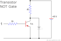
In the following NOT transistor circuit diagram, the current flows through the 1K resistor and through the LED when the switch is open. This turns the LED on. When the switch is closed, however, the transistor turns on and the current flows through the same resistor, but bypasses the LED, turning it off.
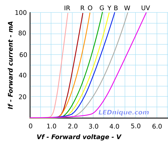
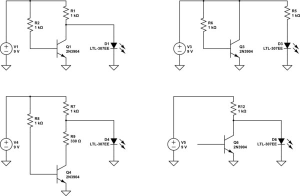
Why isn't the current split between the transistor and the LED? Why does the transistor path get all of the current when the switch is on? Shouldn't there be some current flowing through the LED as well? Why is it being starved of all the current? What would happen if we moved the 1K and placed it in series with the LED? Would it cause a short circuit? Let's say you replaced the transistor, the switch and the gate resistor with a small resistor. Would it split the current then?
I prefer a math-free explanation using analogies since my working memory isn't optimized for it. In other words, my brain has a slow ALU and a tiny set of small registers.


