2
\$\begingroup\$

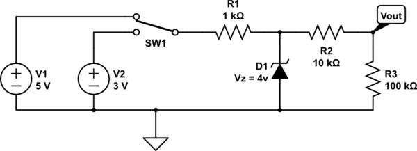
Maybe I don't quite understand how zener diodes work but, I thought that they would block a reverse voltage until it reached a certain threshold (the zener voltage) and above that, they would allow the current to flow. This diagram shows my circuit:
schematic

simulate this circuit – Schematic created using CircuitLab

When the switch is flipped to 5v, I would expect Vout = ~0v because current would flow through D1 instead of R2, but instead, I get Vout = ~3.5v.

When the switch is flipped to 3v, I would expect D1 to block the current and so Vout = ~3v. I get Vout = ~2.7v which is close enough.

I don't have a zener diode to test this with a physical circuit. I wanted to simulate it first so I would know what parts to get. I have tried it in both iCircuit and CircuitLab and both produce the same results.

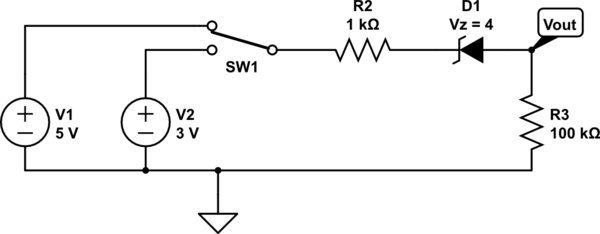
I also tried putting the zener diode directly between SW1 and Vout like this:
schematic

simulate this circuit

This gets me sort of what I expected. When switched to 3v I get Vout = ~0v but when switched to 5v, I only get Vout = ~1.2v.

How do I get Vout closer to 5v when switched to 5v?

\$\endgroup\$
5
  • \$\begingroup\$ you need a series resistor to limit the maximum current through the zener. \$\endgroup\$ Commented May 25, 2015 at 16:44
  • \$\begingroup\$ Your Vout point is directly connected to Ground, so it will always read Zero volts. Replace the right-hand vertical line with a resistor, and put the Vout point at the top right corner of the circuit - then you should see some voltage. \$\endgroup\$ Commented May 25, 2015 at 16:47
  • \$\begingroup\$ @Jim Dearden I just went into CircuitLab and tried both a 1k and 10k resistor ahead of D1. Still didn't give me a voltage at Vout. \$\endgroup\$ Commented May 25, 2015 at 16:49
  • \$\begingroup\$ I have updated the diagrams based on the comments so far. My first diagram is still not doing what I expect. The second sort of does but is lacking (only 1.2V when switched to 5v) \$\endgroup\$ Commented May 25, 2015 at 17:08
  • 1
    \$\begingroup\$ What you're missing in the original circuit is - yes you are correct that the Zener will conduct when the voltage across it is greater than 4v - but it does not drop to a dead short - instead it allows sufficient current to flow to limit the voltage across it to 4v \$\endgroup\$
    – peterG
    Commented May 25, 2015 at 23:29

3 Answers 3

2
\$\begingroup\$

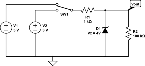
You need a resistor between the switch and zener, and a resistor between the Vout point and ground, like so:

schematic

simulate this circuit – Schematic created using CircuitLab

With the switch up, the Zener will limit Vout to 4 volts.

With the switch down, the Zener will not conduct, and Vout will be 3 volts (less a bit, due to the current drawn by R2)

Without R1, when the switch is up, infinite current would flow through the Zener diode as V1 tries to deliver 5 volts, and D1 tries to hold the voltage to 4 volts.

\$\endgroup\$
4
  • \$\begingroup\$ Is there a way to get Vout = ~0v when current is flowing through the zener and not just limit it to Vz? \$\endgroup\$ Commented May 25, 2015 at 17:11
  • 1
    \$\begingroup\$ You cannot get Vout = 0 just with a Zener diode and resistors. The Zener diode just prevents the voltage across itself from rising above its zener voltage. \$\endgroup\$ Commented May 25, 2015 at 17:14
  • \$\begingroup\$ I guess that is what I misunderstood -- I thought it prevented reverse voltage until it reached it's threshold, then it allowed the voltage to flow. \$\endgroup\$ Commented May 25, 2015 at 17:53
  • \$\begingroup\$ A Zener diode allows current (not voltage) to flow through it if the applied voltage exceeds the Zener reverse breakdown voltage. A resistor is required in series with the Zener diode to limit the current to a safe value. \$\endgroup\$ Commented May 25, 2015 at 21:59
2
\$\begingroup\$

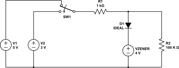
If it will help, you can consider an ideal zener as a voltage source with a diode in series. Then your circuit becomes

schematic

simulate this circuit – Schematic created using CircuitLab

Now, when 5 volts is selected, D1 is forward biased and the R1/D1/R2 junction is held at 4 volts. When 3 volts is selected, D1 is reverse-biased, so VZENER is essentially disconnected from the circuit, and the junction will be at 2.97 volts.

Keep in mind that zeners don't use ideal parts, so the actual voltage when V1 is connected will depend somewhat on the actual level. That's why your second circuit gave you 1.2 volts rather than 1 volt.

\$\endgroup\$
0
\$\begingroup\$

The onlyway to get what you want is to use the optocoupler.First reduce the voltage by a regular diode,the 5v supply would be pulled down to 3v and the 3v supply would become 1v.Now only 3v can light up the LED bright enough to cause a current at the phototransistor.

\$\endgroup\$
1
  • 1
    \$\begingroup\$ Did you not read Peter Bennett's answer which the OP (original poster) accepted as correct? Welcome to EE.SE. \$\endgroup\$
    – Transistor
    Commented Oct 28, 2019 at 17:56

Your Answer

By clicking “Post Your Answer”, you agree to our terms of service and acknowledge you have read our privacy policy.

Not the answer you're looking for? Browse other questions tagged or ask your own question.