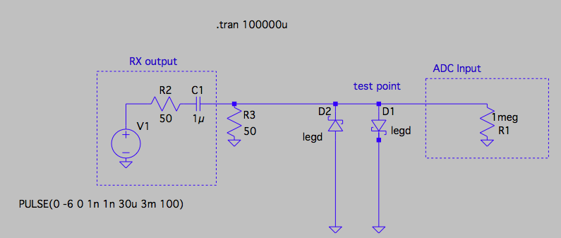
The mbrb1545ct is a very beefy diode that can pass current approaching 10 ampere. With such a big current capability comes a high capacitance.
Take a look at figure 5 in the data-sheet. You'll see a capacitance ranging between 1000pf and 250pf based on the reverse voltage. That is a lot of capacitance and will negatively affect your 5Mhz signal because the diode will - while it does not conduct - work as a buffer capacitor or a low-pass filter.
I would pick a diode that has enough current capability while giving you the lowest capacitance and lowest reverse recovery time.
Since your signal is +/- 6V and it has an internal resistance of 50 Ohm the diode would need to pass 120mA worst case.
One suggestion (that I just pulled from memory because I was researching fast diodes lately and saved one of the data-sheets of a part that I liked a lot) would be to use the BAW76 or so.
It can handle 300mA continuous current, so it'll be fine with the input signal.
It has an internal capacitance of 2pF worst case. That's two magnitudes better than the rectifier diode you've chosen, and it is unlikely that it affect your signal much. The reverse recovery time is 4ns which equates 250Mhz, so the switching speed of the diode won't affect your 5Mhz signal either.
It is not a Schottky but an ordinary high-speed silicon diode so the clamping voltage will be higher than 0.5V. You can compensate for that by putting a two resistor voltage divider after the diode clamp circuit to scale down the clamped voltage to your range.
Note with all diodes the clamping voltage depend on the current passing through the diode. The more current the diode will conduct, the higher the clamping voltage will be. This is a property for all diodes, so you'll never be able to build a super exact voltage clamping circuit without help from active components like OpAmps.
 mbrb1545ct datasheet:
http://www.vishay.com/docs/88670/br15xxct.pdf