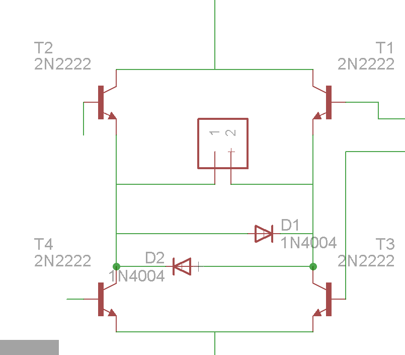
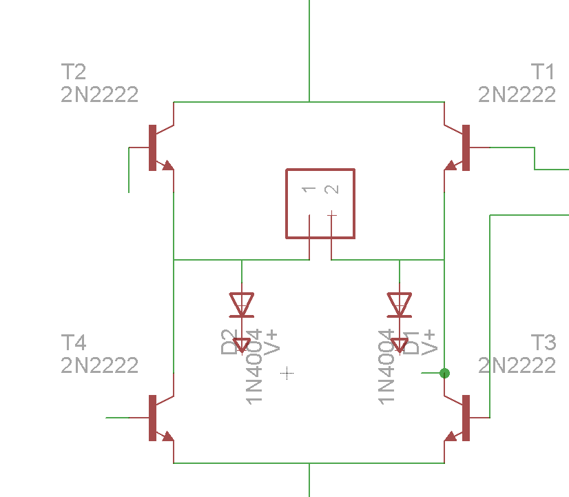
 so here's the situation, i have a motor and i am controlling it with a bunch of transistors and an arduino, so i think i need a flyback diode to protect the transistor and my arduino, problem is i am printing the circuit on a single layer PCB , and i have to connect the motor connected as shown, transistors are used as switches and they are activated depending on the desired direction of the current, the problem is when i added the 2 parallel diodes, however was the direction of the current one of the branches will short the circuit, so i suggested this change in the second pic, this way current will go back to the battery, problem is i dont have any idea if that's gonna work and i don't even know how to test it

-
\$\begingroup\$ "as shown"? pics aren't showing. \$\endgroup\$– tcrosleyCommented Jul 23, 2015 at 1:00
-
\$\begingroup\$ i am sooo sorry, i guess i closed the browser before it finished uploading \$\endgroup\$– user28324Commented Jul 23, 2015 at 2:25
-
\$\begingroup\$ In your first picture you're shorting out the motor with the diodes. In your second picture you're missing the diodes to ground. \$\endgroup\$– GolažCommented Jul 23, 2015 at 11:49
1 Answer
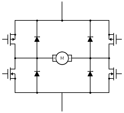
Your pics aren't showing, but I'm assuming you have something that resembles an H-Bridge for your motor. If so, you should connect your diodes like in this schematic:
In this schematic, you can ignore the MOSFETs on the left and right side. The wire off the top is the battery positive, the bottom is ground.
This may look like you're creating a short, but you're not. Instead, you're providing somewhere for the potentially massive flyback current to go when the motor stops or changes direction.
-
\$\begingroup\$ i have only 2 diodes , will it work or do i need 4? \$\endgroup\$ Commented Jul 23, 2015 at 8:52
-
\$\begingroup\$ @user28324 If you have a full H-bridge and you're driving the motor both ways, you need all 4. Because the polarity of back EMF changes with direction the motor is running. \$\endgroup\$– GolažCommented Jul 23, 2015 at 11:47

