1
\$\begingroup\$

I've got an unregulated input voltage of 5V..20V from which I need to drive a shunt reference LM4040 at 3.3V. According to my calculations a shunt resistor of 1.5kOhm would result in a peak current of (20V-3.3V)/1.5kOhm = 11mA and dissipated power of 3.3*11mA=36mW. The current is alsready close to the rated maximum of 15mA. At 5V the a 1.5kOhm shunt will only give around 1.1mA of output current which seems low since the STM32 datasheets states VREF+ current consumption of 500µA but does not state wheter this is for one ADC or all three sampling.

Given these constraints I'm thinking about placing a simple PNP current source in front of the shunt reference to supply a constant 5mA independent of the supply voltage. I also hope to reduce self heating the reference and therefore improve stability.
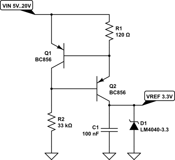
schematic

simulate this circuit – Schematic created using CircuitLab

Does this make sense? Am I missing something, are there gotchas I need to be aware of or is there a better solution?

Admendum

Out of curiosity I simulated the PMOS version of the circuit, which also kind of works. However, I have no clue how to calculate the current. Can someone give a pointer where to start analysis of MOSFET in linear mode?

\$\endgroup\$
0

2 Answers 2

3
\$\begingroup\$

Firstly, your calculation is wrong for the power dissipation in the regulator - the voltage across the regulator is clearly 3V3 and the current thru it at maximum voltage (20V) is (20 - 3.3)/1k5 = 11mA, therefore power dissipated is 37 mW. The resistor will be dissipating most of the power (183 mW).

However, if you were still intent on using a current control circuit then for Q2 to be operating in a "proper area" it needs about 0.7 volts across base and emitter. Given that for Q1 to operate it needs 0.7 volts across its base and emitter, it follows that the base of Q2 will be about 1.4 volts below the 5V rail - this is sailing a little close to putting Q2 into saturation and not being able to supply the current needed to feed the shunt regulator.

I'm not saying it won't work - I'm saying I would want to simulate this to make sure there was enough headroom.

On the other hand if you used a basic PNP current mirror you would be significantly further away from saturation and I'd be happier with this as a "goer" from the start. The current regulation doesn't need to be that precise so maybe consider this as an alternative idea.

\$\endgroup\$
1
  • \$\begingroup\$ Thanks for the pointer. I've corrected the dissipated power. \$\endgroup\$
    – Arne
    Aug 17, 2015 at 13:24
2
\$\begingroup\$

Looks okay to me. You might want to reduce the value of the 33K resistor a bit to cover off temperature and component value extremes.

\$\endgroup\$
1
  • 1
    \$\begingroup\$ I agree. At 5V in, R2 is carrying only about 100 uA, about half of which is being supplied by the base of Q2, which means that Q1's collector current is only abut 50 uA. I think the whole thing would be more stable if R2 were reduced to 10K or less. \$\endgroup\$
    – Dave Tweed
    Aug 14, 2015 at 13:24

Your Answer

By clicking “Post Your Answer”, you agree to our terms of service and acknowledge you have read our privacy policy.

Not the answer you're looking for? Browse other questions tagged or ask your own question.