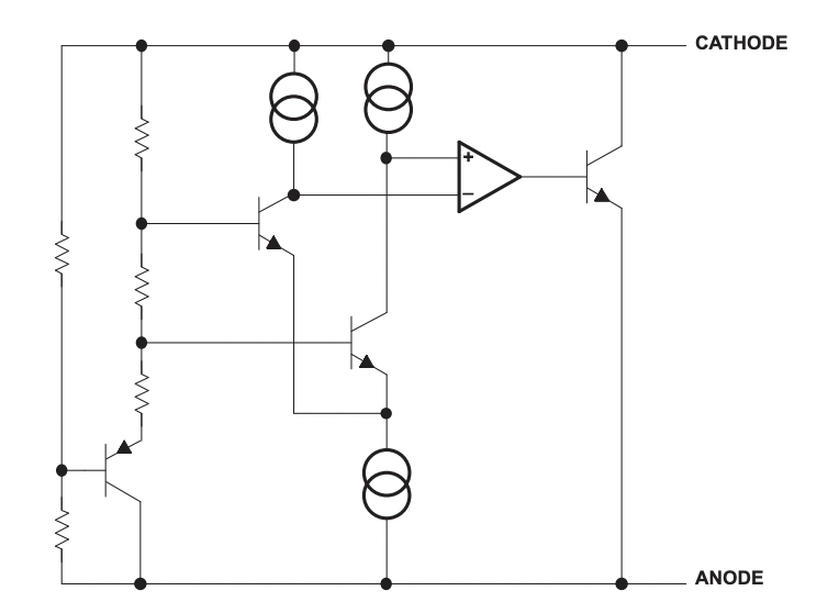
Could you help me understand how this shunt voltage reference circuit operates? Cathode connects to Vin while Anode typically connects to ground (unless floating). This circuit is from the LM4040 datasheet.
2 Answers
For context, this is generally connected with anode to ground and cathode pulled up through a resistor, like a Zener diode. Although other configurations are possible, that's the way to look at it for this explanation.
The PNP transistor is just part of the voltage divider to get the inputs for the emitter-coupled differential amplifier that the two NPNs comprise. This diff amp is probably trimmed in ways not shown so that the NPN driving the negative input has a slightly higher B-E threshold than the one driving the positive input. Normally these would be matched, but in this case we need a controlled input offset. The inputs to that diff amp come from the voltage divider, and are proportional to the input voltage.
That offset is achieved when Vc-Va is equal to the specified voltage. If it's any lower than that, the differential input offset won't be overcome, and the transistor driving the negative input (we'll call it Q1) turns off. The other one (Q2) turns on, pulling the positive input low, resulting in the op amp driving the base of the output transistor (Q3) with a lower voltage. The transistor draws less current, and presumably the cathode-anode voltage increases.
If Vc-Va is higher than the specified voltage, Q1 turns on and Q2 off. This drives the negative input lower, increasing the op-amp output and driving Q3 harder. This will presumably decrease the output voltage as Q3 draws more current.
There is a basic description of operation in the datasheet, right below the image you captured.
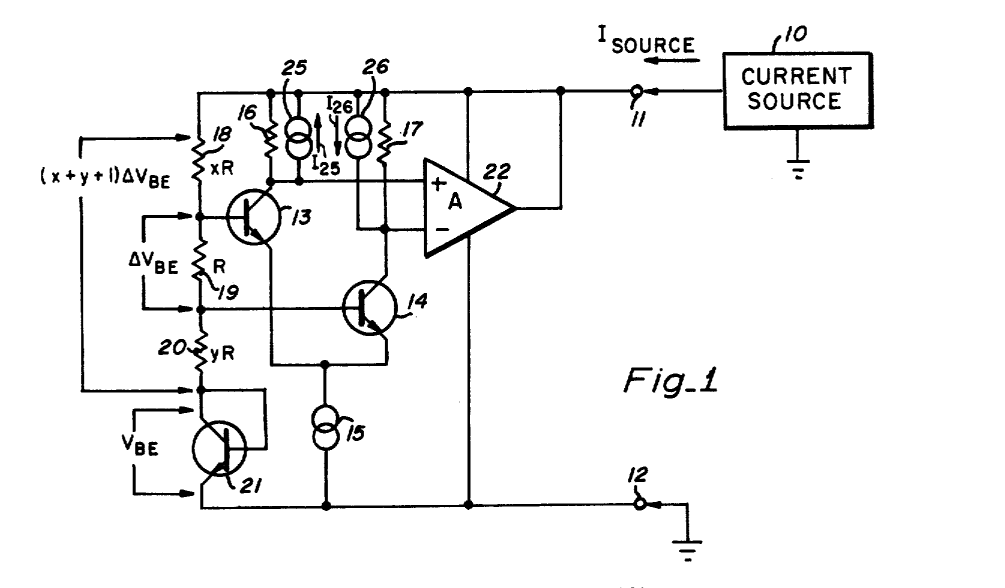
Your best bet is to thoroughly read US4249122A (Feb 3, 1981, inventor Robert Widlar, assignee National Semiconductor). One variation shown below:
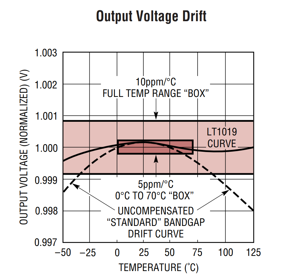
The PNP transistor in the LM4040 is part of the first-order curvature correction for the raw bandgap reference. A bandgap reference without curvature correction has a convex curvature as shown in the LT1019 datasheet (a curvature-corrected series reference rather than a shunt reference):
Note that with a shunt reference it is ideally fed with a current source, or less ideally by a series resistor to a voltage source, not "Vin". Lower resistor values mean poorer line regulation.


