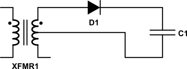
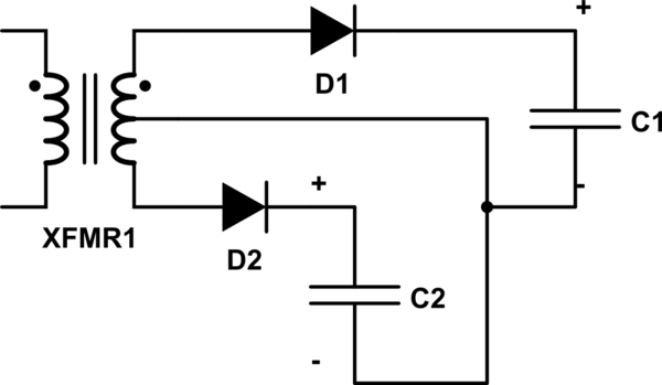
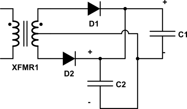
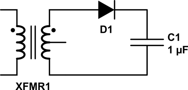
I'm currently constructing a power supply for a small helium neon laser tube, based on this circuit:
The output of a centre tapped transformer (small neon sign transformer), is rectified by two high voltage diodes, smoothed by around 1uF of capacitance and fed through a ballast resistor which regulates current to the laser tube itself (due to it's negative resistance characteristic). I know this isn't the most efficient power supply design, with significantly more energy being lost as heat in the resistor than is consumed by the tube itself, however, the entire system into which this laser is being integrated is intended to resemble quite accurately, the early helium neon lasers of the 1960's, which as mentioned in the below link, used a power supply similar to this.
This brings me to my question. On the site where I found the original schematic (here), the author mentions a voltage of 7.07kv across the capacitors (5*1.414), but it seems to me, as both taps are being utilized, the voltage would actually be 14.14kv, the peak voltage of the 10kv input, is this correct, or am I missing something?
Thanks in advance for any help!


