3
\$\begingroup\$

I am looking for a way to test a neon sign to determine the correct power supply size.

The power supplies come in a variety of different sizes but the most common are:

6kV and 10kV and a working frequency of 36-41KHz.

The power supplies are self adjusting and there is a guideline as to the amount of glass that is to be connected to them based on diameter of the tube and gas pressure.

I am looking for a solution that allows us to take the sign and measure the output of the power supply.

The idea is to be able to make sure we never load them past 80%.

We bought a Fluke Multimeter only to find out that we are limited to 1000V and do not want to destroy it in the name of progress.

What are cost effective solutions to be able to make this measurement. Will adding something like a high voltage probe work in this application with the high frequency? Or are we better off biting the bullet and purchasing something completely different?

\$\endgroup\$

3 Answers 3

3
\$\begingroup\$

You're probably going to need a high voltage oscilloscope probe if you want to do this safely and effectively.

Tektronix has a good selection here: https://www.tek.com/high-voltage-probe-single-ended

Sadly, these aren't cheap. The one rated for 20kV (P6015A) will run you about $2000. However, for that price you get to not worry as much about having to debug a high voltage measurement setup. In terms of time saved, it is very cost effective compared to paying an engineer or technician to design their own high voltage test setup.

You will probably also want an oscilloscope to go with it (a cheap one will do), but you can also get BNC->Banana Plug adapters to plug it into a multimeter (though I don't know how well most multimeters work at those kind of frequencies).

\$\endgroup\$
1
  • \$\begingroup\$ Good answer +1. The CT-4026 probe is $440 and maybe another $300 for a scope. Note the derating from 18kV to 15kV at 40kHz. If the center is grounded two measurements may be required (one measurement from each lead to ground and add). \$\endgroup\$ Commented Sep 15, 2017 at 5:23
3
\$\begingroup\$

All you need is a high voltage probe for your Fluke multi-meter.

They come in various voltage capabilities; 6, 15 and 40 kV.

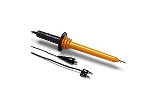
It looks like the 15 kV model should be adequate for you:

enter image description here

Be aware that to understand the power loading on your high voltage power supply you need to measure both the voltage and the current through your sign element.

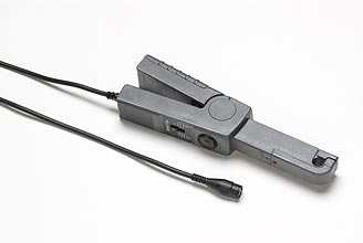
To measure current you could measure the primary current in the power supply to get a reasonable indication (though it includes current due to output power plus current due to power losses in the transformer) of the total power consumed. Something like this for your Fluke should work:

enter image description here

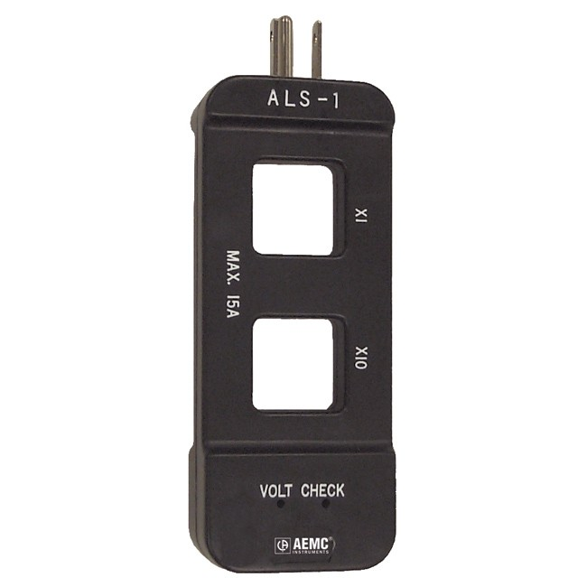
Personally I use a Tenma 72-6130 multimeter with an inbuilt current probe. I also use an ExTech/AEMC ALS-1 mains line splitter/breakout with X1 and X10 current loops to make current measurements very easy. There are a slew of line splitters available, and they are very cheap.

enter image description here

\$\endgroup\$
3
  • \$\begingroup\$ I'd just add ... you probably don't want to be re-plugging probes around a HV setup mid-measurement, so a second multimeter would be handy. \$\endgroup\$
    – user16324
    Commented Sep 15, 2017 at 9:13
  • \$\begingroup\$ A second meter might be convenient, but certainly not required. The probe should never be permanently attached to a measuring point, it's meant to be manually used. The current probe can be permanently attached to a mains lead. It's double insulated and is not a direct connection. \$\endgroup\$ Commented Sep 15, 2017 at 15:29
  • \$\begingroup\$ Thank you for the info. I will put this all together and test it over the weekend to see how it works and report back. \$\endgroup\$
    – Jeff
    Commented Sep 15, 2017 at 16:17
0
\$\begingroup\$

View the neon energy as tiny lightning strikes. Holding the tip of a scope probe near the glass will induce some voltage into the scope probe. Sliding that along the glass tube will vary the voltage, because the ionized gas acts as a voltage divider.

But how to calibrate this effect?

\$\endgroup\$

Your Answer

By clicking “Post Your Answer”, you agree to our terms of service and acknowledge you have read our privacy policy.

Not the answer you're looking for? Browse other questions tagged or ask your own question.