15
\$\begingroup\$

Just one minute! I am not trying to understand what negative feedback does eventually, or why it should be used. I am trying to understand how the circuit reaches steady state, and how, step by step, the negative feedback causes Vout to be the same as Vin. This has not been addressed adequately in other answers.

enter image description here

Let's assume the op-amp has a gain of 10,000, a supply of 15V, and Vin is 5V.

According to my understanding, this is how it goes:

  1. \$V_{in}\$ is 5V, so \$V_{out}\$ should be 50,000V. However, it is limited to 15V by the power supply of the op-amp.
  2. \$V_{out}\$ is then applied back to \$V_-\$, but it is subtracted from \$V_{in}\$ due to it being negative feedback
  3. So the differential input voltage is now 5V - 15V = -10V
  4. This is then amplified to -15V by the op-amp (because of saturation)
  5. Now -15V is applied to \$V_{in}\$ through negative feedback, but it is added to 5V, due to double negative
  6. So now differential input is 20V, and \$V_{out}\$ is 15V (due to saturation)
  7. It seems that each time the op-amp will reach saturation, but just invert the output

I have obviously done something wrong here. The output is never going to stabilize at 5V in this way. How does it actually work?


Due to the excellent answers, I (think I) have understood the operation of negative feedback. According to my understanding, this is how it goes:

Let's say for simplicity that the input is a perfect step to 5V (otherwise the output would follow the transient input, making everything 'continuous' and difficult to explain in steps).

  1. In the beginning, the input is 5V, and right now the output is at 0V, and 0V is being fed back to \$V_{in}\$
  2. So now the differential voltage \$(V_+ - V_-)\$ is 5V. Since the gain of the op-amp is 10,000, it will want to produce an output of 50,000V (practically limited by the supply voltage), thus the output will start to increase rapidly.
  3. Let's consider the point in time when this output reaches 1V.
  4. Right now the feedback will be 1V as well, and the differential voltage will have fallen to 4V. Now the 'target' voltage of the op-amp will be 40,000V (because of the 10,000 gain, and again, limited to 15V by the power supply). Thus V_out will keep on increasing rapidly.
  5. Let's consider the point in time when this output reaches 4V.
  6. Now the feedback will be at 4V as well, and the differential voltage will have fallen to 1V. Now the op-amp 'target' is 10,000V (limited to 15V by the supply). Thus \$V_{out}\$ will still keep on increasing.

The emerging pattern is: the differential input causes increase in V_out, which causes increase in feedback voltage, which causes decrease in differential input, which decreases the op-amp 'target' output voltage. This cycle is continuous, meaning we can split it into even shorter intervals for investigation. Anyhow:

  1. Let's consider the point in time when this output reaches 4.9995V. Right now the feedback is 4.9995V, so the differential voltage will fall to 0.0005V \$(V_{in} - V_- = 5V - 4.9995V = 0.0005V)\$. Now the target of the op-amp is \$0.0005V*10,000 = 5V\$.

However, if the op-amp reaches 4.9998V, now the differential voltage will be only 0.0002V. Thus, the op-amp output should decrease to 2V. Why doesn't this happen?


I believe I have finally understood the process:

The op-amp output cannot reach 4.9998V. Because as soon as \$V_{out}\$ increases above 4.9995V, the feedback will also increase, causing differential input to decrease, bringing the op-amp output back to 4.9995V.

And if the op-amp output decreases to below 4.9995V, the feedback will decrease, causing the differential voltage to increase, bringing the op-amp output back to 4.9995V.

The last two points are the essence of negative feedback. \$V_{out}\$ has stabilized as close as possible to \$V_{in}\$. If the gain were higher, the difference in \$V_{out}\$ and \$V_{in}\$ would be smaller. If gain reaches infinity, then output voltage is exactly equal to input voltage, and because of feedback being exactly equal to \$V_{in}\$, there would be 0 differential voltage, and a virtual ground would be create between the two inputs.

\$\endgroup\$
7
  • 3
    \$\begingroup\$ If you assume the output transition time is not zero, everything will become clear. \$\endgroup\$
    – Eugene Sh.
    Commented Sep 18, 2015 at 21:39
  • 1
    \$\begingroup\$ Depends on why do you need it. \$\endgroup\$
    – Eugene Sh.
    Commented Sep 18, 2015 at 21:49
  • 1
    \$\begingroup\$ You can't describe it step by step. There are no steps. It's continuous. All the 'then's in your question are fallacious. Everything happens at once. \$\endgroup\$
    – user207421
    Commented Sep 18, 2015 at 22:49
  • 3
    \$\begingroup\$ Even a continuous situation can be broken down into steps by inspecting it at important time intervals, in order to aid understanding. \$\endgroup\$
    – Hassaan
    Commented Sep 19, 2015 at 11:04
  • 1
    \$\begingroup\$ You need to model the opamp with a differential equation to get some idea of the dynamics. Try something like \$\dot{v_o} = - v_o + K (v_+-v_-)\$, with \$v_- = v_o, v_+ = v_{\text{in}}\$. (I'm taking the time constant to be one for simplicity.) \$\endgroup\$
    – copper.hat
    Commented Sep 20, 2015 at 1:13

6 Answers 6

12
\$\begingroup\$

"Vin is 5V, so Vout should be 50,000V."

Why? The OpAmp amplifies the the difference between the + and - inputs, not just the value on the + input!

OK, you might start with: the output is at 0V, and the input (connected to the + input) is 5V. What you have done is apply a 5V step to the input.

Now what happens is that the OpAmp starts to rise the voltage on the output. It can't do this at once, so it will rise 'slowly' (for some rather fast value of slowly, which has a technical name in OpAmp world: the slew rate, which is an importnat charactreistic of a real OpAmp). When it reaches 5V, this is fed back to the negative input, at which time it compensates the 5V at the + input, so the OpAmp no longer tries to rise its output level. (To be really accurate: this happens a little bit earlier, when the difference is 5V/10k.)

Depending on timing characteristics, the output might 'slowly' settle to 5V, or overshoot the 5V, drop below 5V, etc (oscillate towards 5V). If the circuit is designed badly the oscillation might increase (and never end).

\$\endgroup\$
1
  • \$\begingroup\$ Wouter is correct - between step 1 and step 2 (in the question) is a whole load of things that make step 3 onwards basically redundant. \$\endgroup\$
    – Andy aka
    Commented Sep 18, 2015 at 23:02
11
\$\begingroup\$

Most Basic Interpretation:

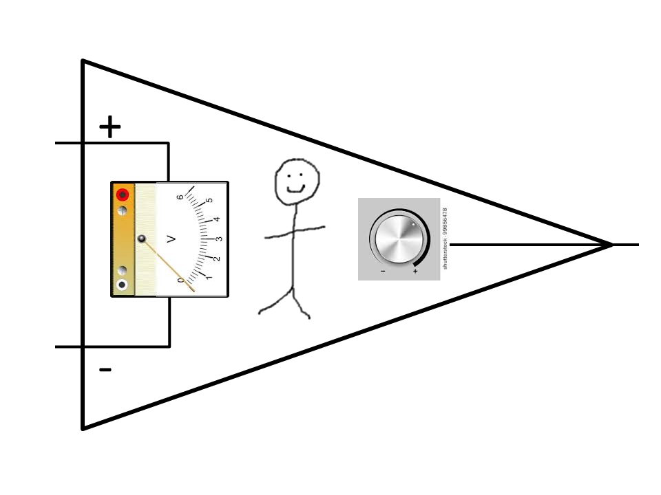
Here is my intuitive way to understand a given op amp circuit by personification. Picture a little dude inside the op amp. The little dude has a display that indicates the difference in voltages between the + and - inputs. The little dude also has a knob. The knob adjusts the output voltage, somewhere between the voltage rails.

dude

The goal of our little friend is to make the difference between the two voltages zero. He will turn the knob until he finds the voltage on the output that, based on the circuit you connected to it, results in zero difference on his display.

So in "sequential" steps:

  1. The input to the buffer circuit is at 5V. Let's assume that the output knob is initially at 0V.
  2. Since the input is connected directly to the output in the buffer configuration, the difference that is on the little dude's display is 5V. He is not happy about that.
  3. The little dude starts turning the knob to increase the voltage output. It keeps getting closer and closer.
  4. Finally, when he sees 0V on the display he stops changing the knob. The output will now be at 5V.

Inside an Ideal Op Amp:

It is not actually a little dude inside an op amp: it's math! Here is a representation of what we are trying to implement in an op amp:

schematic

simulate this circuit – Schematic created using CircuitLab

This will achieve what the little dude was trying to achieve with some limitations:

  • The little dude could figure out which way to turn the knob, but this can't. We have to hook it up such that increasing the output decreases the difference.
  • There will be a tiny error if the "Lots of gain" is not actually infinity.
  • We have to consider carefully whether the circuit will be stable. There's quite a bit out there on this topic.

A Real Op Amp:

Here is what a real op amp (the 741) looks like on the inside:

op amp

These transistors implement the mathematical representation above.

It is important to keep in mind that there are a whole host of practical issues that must be addressed when using a real op amp. To name a few:

  • Bias currents
  • Noise
  • Common mode input voltage
  • Current output
  • Supply voltages
  • Power dissipation
  • Dynamic behavior and stability

But in all op amp circuits, my mind always starts with the "little dude" explanation to get an idea of what is going on. Then, if needed, I extend this with mathematical analysis. Finally, also if needed, I apply practical knowledge of what is needed to meet an applications requirements.

\$\endgroup\$
4
\$\begingroup\$

An opAmp operates in continuous time and not in discreet time. This means that no action can occur instantaneously and actions do not happen in steps. Even if a switch is flipped to connect a voltage to the + pin there is still a transient rise time in the input and the out put continuously follows. This is very commonly described as opAmp action. A spice model is just that, a model. The model does not and can not incorporate all of the nuances that are in the opAmp. If you want to study the transient effects of an opAmp then buy one and look at it with an oscilloscope. That is the only way you will be able to study the effects.

\$\endgroup\$
4
\$\begingroup\$

In the real world, op amps have a limited slew rate. For some kinds of op amps, the slew rate can be very fast, but it's never quite instantaneous. When the "+" input of the op amp is higher, the output will rise very quickly until it reaches the positive rail or the "+" input is no longer higher than the "-" input. When the "-" input is higher, the output will fall very quickly until it reaches the negative rail or the "-" input is no longer higher than the "+" input.

In most properly-designed circuits that use op amps, the aspects of circuit behavior necessary to meet requirements should be satisfied equally well for a significant range of output slew rates. In the case of the voltage follower, for example, the slew rate will add a short delay between the time the input changes and the time the output reaches the same value, but it won't affect the value reached by the output.

\$\endgroup\$
3
\$\begingroup\$

Actually, the phenomenon you describe used to be a real problem, way back in the dark ages (1970s). The venerable LM310 Voltage Follower data sheet contains the application hint (bottom of page 2) which recommends a 10k ohm input resistor in order to maintain stability.

Also note that your argument can be applied to any op amp circuit, and dealing with your objection requires consideration of amplifier frequency response, which is way more than I can cover. Let it suffice to say that, on the one hand, the output does not change instantaneously (limited slew rate mentioned by other responders, and on the other hand there are consideration of how the internal circuitry responds to changes as well.

What actually happens has been described by others: the output responds to bring the difference between the two inputs to zero, and if the circuit is properly designed will eventually stay there. But just to show you that the subject is complicated, consider that if you slow the output down too much (by putting a capacitor to ground on the output) you can also cause the amp to oscillate.

I'm sorry I can't give more details, but it's pretty clear you need a lot more background before I could even try to explain it.

\$\endgroup\$
0
\$\begingroup\$

The gross answer is that the opamp's output will slew to whatever voltage is needed in order for the noninverting (+) and inverting (-) inputs to be at the same voltage. Consequently, if the + input is set to, say, 5 volts, the output will servo to 5 volts so that the - input will be at 5 volts, assuming the opamp's rails will allow that to happen.

In reality, though, the output never really settles down and is always servoing above and below the voltage on the + input.

How much is dependent on the opamp's gain and bandwidth and on the external circuitry, but that's a whole different question.

\$\endgroup\$

Your Answer

By clicking “Post Your Answer”, you agree to our terms of service and acknowledge you have read our privacy policy.

Not the answer you're looking for? Browse other questions tagged or ask your own question.