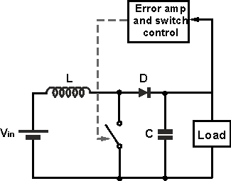
Is it the same as buck converter? when a decrease in load resistance , more current will flow through the inductor
1 Answer
The energy received by the load comes from the energy stored in the inductor. To keep the voltage across the load stable, a certain amount of energy needs to be transferred many times per second and, if the load resistance reduces, either that energy level has to increase or, the rate at which it transfers has to increase.
Either way results in an increase of current in the inductor. However, in its simplest form, both buck and boost have to use an analogue feedback system (error amplifier and switch control) to perform a duty cycle or frequency (rate) adjustment on the switching element in order to regulate voltage for changing load conditions: -
Here's a simple example of trying to regulate 10 V on the output from 5 V on the input with a load resistance of 10 ohms.
When the switch closes for a certain period of time, current ramps up in the inductor linearly (given a constant flat DC input voltage) and then the switch opens. At this point the energy (I'm using "W" so as not to confuse "E" with voltage) stored in the inductor is: -
W = \$\dfrac{Li^2}{2}\$
This energy then feeds the capacitor and load and, assuming the output voltage is already at 10V, all that energy replaces the energy removed from C due to the load taking current. At 10 volts and 10 ohms the power is 10 watts so, providing enough energy is transferred per second, the output remains at 10V. Remember that power = rate of consumption of energy per second.
If the switching frequency is 100 kHz, the required transfer energy per cycle is 10 watts/100k = 100 uJ. If the inductor is 10uH then it needs to store 100 uJ and, to store 100 uJ, you'll need a current of: -
\$i = \sqrt{\dfrac{2W}{L}}\$ = 4.47 amps
But how long does it take to infuse the inductor with 100 uJ? We use the following formula and rearrange to calculate \$dt\$: -
V = \$L\dfrac{di}{dt}\$
V is the input supply voltage that sources the current to charge the inductor and di is the current change over that period of time. For discontinuous operation (simplest to explain) the current starts from zero and must rise to 4.47 amps hence di is 4.47 amps.
Therefore \$dt\$ = 8.94 us.
Given the switching frequency has a period of 10 us this means the duty cycle in this simple example is 89.4 %.
Basically a buck or a boost only know about energy transfer and it requires a seperate error amp to control duty cycle (as in the example above). If the load current dropped to zero, the duty cycle has to drop to zero else the capacitor will continue charging up to some really high voltage then breakdown either itself or the switching transistor.

