1
\$\begingroup\$

How to calculate the power efficiency of zener diode regulator?

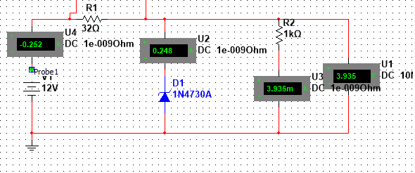
enter image description here

Is it correct to calculate it as the ratio of power delivered to load to the total power drawn from input source?

If I am correct, would the efficiency of circuit shown in the schematic below is 0.5% ?

EDIT

The maximum current zener can handle in this case is around 240mA.

Based on this,

$$ \frac{Vin - Vz}{Imax} = \frac{12-3.9}{240} = 32 Ohms $$

Am I correct?

Is efficiency Vout/Vin or Pout/Pin ?

\$\endgroup\$
5
  • \$\begingroup\$ Max possible efficiency = Vout/Vin. | For maximum efficincy loaded, size R1 so Izener = Iload max when there is no load and Vin is Vin_min_possible. This makes the zener JUIST drzaw no current when max load I is drawn. As zeners have soft curves make R1 slightly smaller so zener draws slightly more than Ilaodmax when cct is unloaded. \$\endgroup\$
    – Russell McMahon
    Commented Oct 9, 2015 at 11:09
  • 1
    \$\begingroup\$ Sizing R1 to run the zener at maximum dissipation is certainly one way of doing it. It has the benefit that if the load draws a variable current, the zener current changes little, so the terminal voltage stays relatively constant. Unfortunately, that's the only thing going for it. Generally, R1 is sized to pass a bit more than the load current. Regulation is then poor, but if you want better regulation, you usually go to a three terminal regulator, rather than burn power. \$\endgroup\$
    – Neil_UK
    Commented Oct 9, 2015 at 12:49
  • \$\begingroup\$ Harry, there are several strategies for desiging a Zener regulator, depending what's most important (variable load, cheap/low-power Zener etc.) I'm hardly the expert on this since I seldom use this circuit. Adding a pass transistor improves the efficiency considerably because the current sunk through its base diminishes by division with the Hfe of the transitor (typically 100). But with any linear regulator, you can't get away from the resistive/linear losses across the series element. I'll give you some link shortly (the don't fit in this comment). \$\endgroup\$ Commented Oct 9, 2015 at 14:15
  • \$\begingroup\$ Strategies/calculators: hyperphysics.phy-astr.gsu.edu/hbase/electronic/zenereg2.html, hyperphysics.phy-astr.gsu.edu/hbase/electronic/zenereg.html#c2, reuk.co.uk/Zener-Diode-Voltage-Regulator.htm Background (including improved circuits that aren't just a Zener regulator): ko4bb.com/e102/e102-4.php And the following discusses mainly improved regulators using a pass transitor. bristolwatch.com/ele/zener_power_supply.htm HTH \$\endgroup\$ Commented Oct 9, 2015 at 14:25
  • 1
    \$\begingroup\$ And regarding your added question: the efficiency formula is Pout/Pin. (See en.wikipedia.org/wiki/Energy_conversion_efficiency) What @Russell McMahon says is that Pout/Pin is always less (or at best equal to) Vout/Vin for a linear regulator. \$\endgroup\$ Commented Oct 9, 2015 at 14:39

1 Answer 1

3
\$\begingroup\$

I gather you're not impressed by 16mW to the load while taking 3 watts from the battery? Yes, efficiency is Pout/Pin.

Shunt regulators are not used for efficiency, they are used for their simplicity.

Most people wouldn't use such a low value resistor as R1 for that load. How did you choose the value? Think about what the constraints are on the value of R1.

Use a three terminal series pass regulator if you want to waste less power. With a 4v load, and a 12v source, an ideal 3 terminal regulator would not exceed 33% efficiency.

To approach 100%, you would need a switching regulator.

\$\endgroup\$
6
  • \$\begingroup\$ By the way, this is not a simple shunt regulator. There's a series element (the 32-ohm resistor) that blows away 2W. The Zener diode only blows away 1W. \$\endgroup\$ Commented Oct 8, 2015 at 17:59
  • \$\begingroup\$ @RespawnedFluff: the 32 ohm resistor is an essential part of the Zener regulator circuit. If it was not there, you would have the 4 volt zener directly across the 12 volt battery, which would result in a large cloud of magic smoke. That reistor could be a much higher value, to reduce the .25 amp flowing throug the Zener to a more reasonable value. That would increase the efficiency considerably. \$\endgroup\$ Commented Oct 8, 2015 at 18:15
  • \$\begingroup\$ A resistor + zener is a simple shunt regulator. Are you saying you could make a simpler one with just one of those components (from the same 12v voltage source of course)? \$\endgroup\$
    – Neil_UK
    Commented Oct 8, 2015 at 18:18
  • \$\begingroup\$ Yes, you're both right. I was smoking crack apparently. \$\endgroup\$ Commented Oct 8, 2015 at 18:25
  • \$\begingroup\$ N.B. Here's a what I'd consider a more "typical" (for me) setup (in the rare occasion I've used it): imgur.com/wajTWn2 The Zener blows a more limited/reasonable amount of power away until the voltage difference (between the supply and Zener) gets out of hand; typical/acceptable operating point for that is 7-8V. Also, the series resistor there blows away less than the Zener (but still not negligible). \$\endgroup\$ Commented Oct 8, 2015 at 19:39

Your Answer

By clicking “Post Your Answer”, you agree to our terms of service and acknowledge you have read our privacy policy.

Not the answer you're looking for? Browse other questions tagged or ask your own question.