5
\$\begingroup\$

I am trying to understand how laser show galvanometer systems like this one create high-resolution movement, and generate drawings of reasonable precision (w.r.t. minimum beam angular-deflection step size) on a surface several feet away.

enter image description here

The Wikipedia page has very limited information about the modern version, although a paragraph claims high-speed mirror galvanometers are used for laser ablation, marking, etc., which are of course high-precision applications.

Given laser show devices are so popular, but the documentation a bit lacking, I would appreciate an explanation, especially of the closed-loop part which these laser show "scanners" claim to contain.

  • Do they use a stepper motor (and just claim it's essentially closed loop), or do they have a standard DC motor with a magnetic/optical encoder of some sort?

  • Also, what kind of angular resolution is a system like the above linked product, typically capable of?

As may be clear from these questions, I am trying to see if it would be apt to repurpose one of these for my own project, where I need to attain laser-marking at approx. 50-75 microns resolution at a few centimeters away (unfortunately, physical constraints prevent use of a gantry system that might be seen in 2D plotters/3D printers).

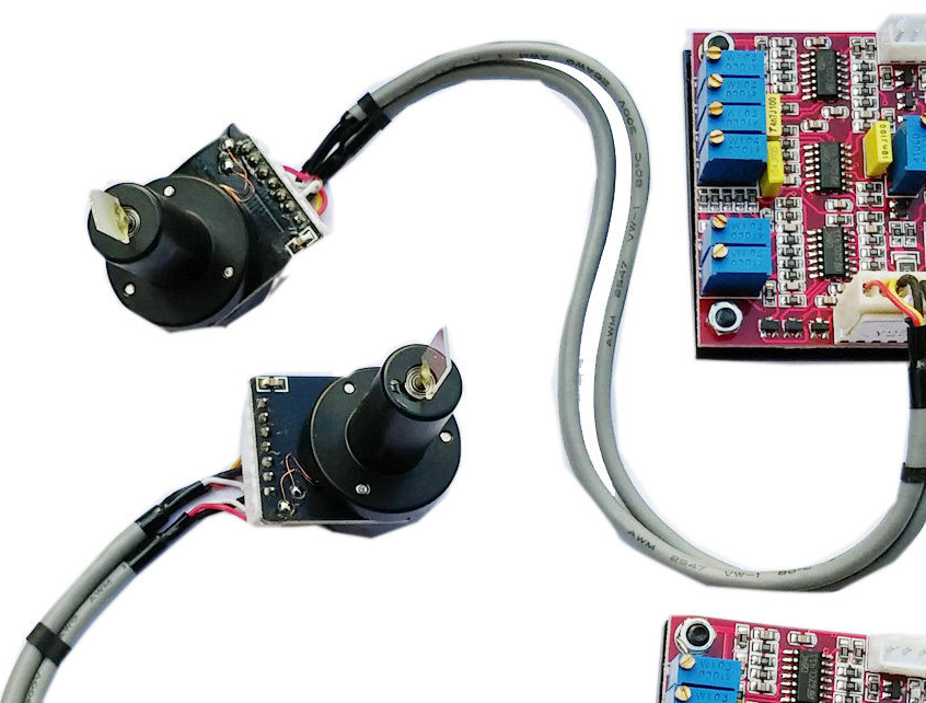
\$\endgroup\$
1
  • 1
    \$\begingroup\$ I think everyone missed the concept of light/galvos synchronization. During the scan the laser diode is turned on/off at particular times. \$\endgroup\$
    – Nazar
    Commented Oct 16, 2015 at 17:48

3 Answers 3

1
\$\begingroup\$

According to camtech there are two types of actuator configurations (moving magnet and moving coil) and two types of positioning detection systems (optical and capacitve) commonly used for galvanometers carrying laser mirrors:

The galvo itself has two major parts: the actuator that manipulates the mirror load and the integral position detector that provides mirror position information to the closed loop system. Two actuator configurations commonly serve today's high-performance systems.

The moving magnet, in which the magnet is part of the rotor and the coil is part of the stator, provides the highest system-resonant frequencies because of its uniform rotor design. The moving coil, in which the coil is integral to the rotor and in which the magnet is part of the stator, offers the highest torque-to-inertia ratio and the highest torque efficiency.

In the two common types of position detectors, the detector element moves as part of the galvo rotor structure. In the moving dielectric capacitive design, a radio frequency source drives two variable capacitors, and the resulting rectified differential currents report the position of the galvo actuator and mirror. In the new optical position detector designs, a light source illuminates parts of four Photocells. Between the light source and the receivers, a moving butterfly like shape casts more or less shadow onto pairs of the receiver cells. The resulting currents report the position of the galvo actuator and mirror.

The design of the positioning detector greatly defines the positioning accuracy of the system, and its inertial and resonant frequency characteristics affect the speed of the system. The compact, low-noise and low inertia features of Cambridge Technology Inc.'s patented optical position detectors provide higher speed, smaller size, and reduced cost compared with capacitive devices, without sacrificing accuracy or stability. Moreover, some Capacitive Detectors can emit RF electrical noise that can interfere with nearby electronics in the system, whereas this noise is eliminated with optical position detectors.

The ebay page you link to doesn't detail what internal construction the galvanometers have (neither actuator type nor position detector type), but it does say PID controller for the feedback loop.

\$\endgroup\$
4
\$\begingroup\$

It's not a motor, it's a galvanometer: a system which produces a deflection proportional to current. It's very different from a stepper motor as there are no discrete 'steps'.

A webpage for an example professional galvo unit: http://www.thorlabs.de/newgrouppage9.cfm?objectgroup_id=3770

That does the courtesy of explaining both how it works

The angular orientation (position) of the mirror is optically encoded using an array of photocells and a light source, both of which are integrated into the interior of the galvanometer housing. Each mirror orientation corresponds to a unique ratio of signals from the photodiodes, which allows for the closed-loop operation of the galvo mirror system

...

The Proportional Derivative (PD) servo driver circuit interprets the signals from the optical position detecting system inside the motor and then produces the drive voltage required to rotate the mirror to the desired position.

and also the angular precision of 0.0008° (15 µrad) if you use their special clean power supply.

The light show unit doesn't specify an angular resolution, only a scanner speed in "points per second".

\$\endgroup\$
2
  • \$\begingroup\$ I'm guessing sasha was a bit confused because the Wikipedia page he linked to ("Mirror galvanometer")... kinda fails to link to galvanometer; actually it does but only toward the end of the page. \$\endgroup\$ Commented Oct 16, 2015 at 17:18
  • \$\begingroup\$ According to another page I found (see my answer) it's not necessarily the case that the ebay galvo[s] he found work this way. They could have capacitive position detectors inside. \$\endgroup\$ Commented Oct 16, 2015 at 17:48
2
\$\begingroup\$

According to this guy, a closed loop galvanometer gives you a feedback signal that you can use to detect the current position of the armature.
So, you send a signal to the galvanometer representing the position it should take, then amplify the difference between the feedback signal and the applied signal to correct the position until it matches your desired position.

The example I linked to uses a capacitive feedback, but there are also optical systems and potentiometer based systems.

So, it really is a galvanometer and not some kind of servo or other motor.

That site also goes into detail of building and using the position detector and the needed feedback loop. There are also plenty of technical terms and abbreviations that might help in finding more useful specifications on commercial units.

Accuracy and repeatability will depend on the mechanical parts (bearings) as well as the noise levels in the control circuitry. I couldn't find anything about that. I think you need to look for information on the ILDA test patterns to get started in that direction.

Angular resolution will depend (in part) on the resolution of whatever DAC you are using to drive the galvanometer and also on the driving electronics and feedback circuitry. It will also depend on the scan angle. The scan angle divided by the number of bits of your DAC will give you the theoretical resolution of the scanner.

To get your needed 50 microns at 3 cm distance, you would need an angular accuracy of about 0.095 degrees. Given a maximum deflection of 40 degrees (I find notes that that is the maximum for closed loop systems) then that is only about 420 steps - a 10 bit DAC ought to be enough, though I see units avalaible that take digital input at up to 24 bits.

Points per second is a measure of how fast the galvanometer can respond to changes in angle.

\$\endgroup\$

Your Answer

By clicking “Post Your Answer”, you agree to our terms of service and acknowledge you have read our privacy policy.

Not the answer you're looking for? Browse other questions tagged or ask your own question.