3
\$\begingroup\$

Good Morning All

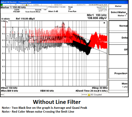
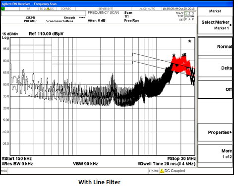
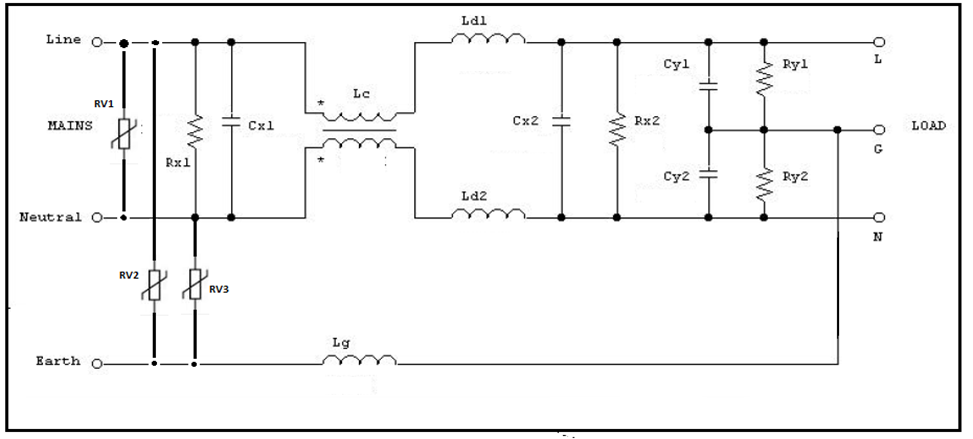
We run Conduction emission Test on Lab with the Line filter and without the line filter. Product was 230V 16A welding Power supply. Below are the graph with line filter and without Line filter.

enter image description here

enter image description here

enter image description here

Question is even with Filter Coonecting I am getting failure on High Frequency Side.(around 22 Mhz to 30Mhz), I tried with Different-Different Core(All most of core manufactures with Ferrite and Nanocrytalline Materials), No of turns, Changing Cx and Cy Value , Single filter and double stage filter, Stack up the Cores Alos. Even with all tried I have the same problem of noise at same frequency.

Please suggest some method to suppress this high frequency noise, I am going next again for lab Testing.

Thanks

\$\endgroup\$
8
  • \$\begingroup\$ You might want to start figuring out what components/traces actually produce that noise and then think about if you can do something about it. E.g. drive FETs less hard. Without schematics and PCB layout no one can tell you what to do about it. Read through existing questions with generic tips. \$\endgroup\$
    – PlasmaHH
    Commented Oct 29, 2015 at 13:46
  • \$\begingroup\$ I don't think there's much more you can do on the filter side regarding suppression of 20-30 MHz. The components that you have to use (because of voltage and current ratings) simply don't filter as much as you would expect because of their parasitics. I'm with PlasmaHH in that you should try to generate less signals in the 20-30 MHz range in your connected load. I'm thinking ferrite cores around the gate of switching transistors etc. \$\endgroup\$ Commented Oct 29, 2015 at 13:49
  • \$\begingroup\$ If nothing you change about the filter makes any difference, then you should consider that perhaps the noise is getting onto the supply between the outside and the filter. Is there much cable inside the box between the inlet and the filter? Can you move the filter nearer the inlet? \$\endgroup\$
    – user1844
    Commented Oct 29, 2015 at 14:14
  • 1
    \$\begingroup\$ Approx Wire length of input inlet to Filter input is 20CM and approx Wire length of filter Ouput to Power Board is 25CM. We run radiated test without the filter and system fail on No laod condition at 37Mhz ,38Mhz and 48Mhz. We never run radiated test with this Filter above, Will do next when lab avilable. Also Y capacitor is added on outside of filter around 33nf each line to earth and netural earth, yes I never added Y cap at input side of filter, will this make difference. Thanks \$\endgroup\$
    – Electra
    Commented Oct 29, 2015 at 14:59
  • 1
    \$\begingroup\$ Revisit the earthing of your line filter .This affects performance at the high end much more than the low end.Remember that a high end conducted fail generaly means that you have a radiated fail to look foward to . \$\endgroup\$
    – Autistic
    Commented Oct 29, 2015 at 19:39

1 Answer 1

2
\$\begingroup\$

1) First let's talk about your filter: Check if the resonant frequencies of the capacitors that you are using are high enough. In the resonant frequency your capacitors will behave as resistors. Above the resonant frequency...as inductors.

IF this is the case, you might test some smaller values of capacitors in parallel with the existing ones (smaller capacitors of a same series usually have higher resonant frequencies).

2) I don't know what switching device you are using (IGBT, MOSFET...), but consider to do some research on RC snubbers in order to attenuate the parasitic currents close to your switching devices.

Best regards

\$\endgroup\$
0

Your Answer

By clicking “Post Your Answer”, you agree to our terms of service and acknowledge you have read our privacy policy.

Not the answer you're looking for? Browse other questions tagged or ask your own question.