1
\$\begingroup\$

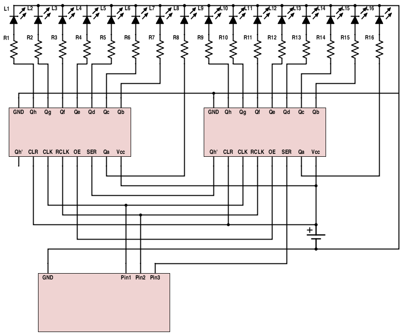
I'm fairly inexperienced in electrical engineer so forgive the simple question. Using a microcontroller (Netduino) and two 8bit shift register (serial in, parallel out) I'm controlling 16 LEDs.

The logic works fine, I was expecting the shift register and lights not to work when I don't plug in the auxiliary power source and just fired up the microcontroller. Right now, the microcontroller is powering all the LEDs and I don't want that.

Even though the schematic isn't perfect, here is my circuit: The resistances are 220 ohms +/- 10%. The shift registers are SN74HC595s.

enter image description here

I know I could add NPN transistors on each of the shift register outputs, but that would require quite some transistors, and most importantly, the microcontroller would still power the shift register.

I did try to use transistors on Pins 1-3 from the microcontroller but the LEDs were still powering on without the external source of power.

As a secondary point, I know I should add one/some capacitors, but I'm not exactly sure where beside maybe a large one around the power source.

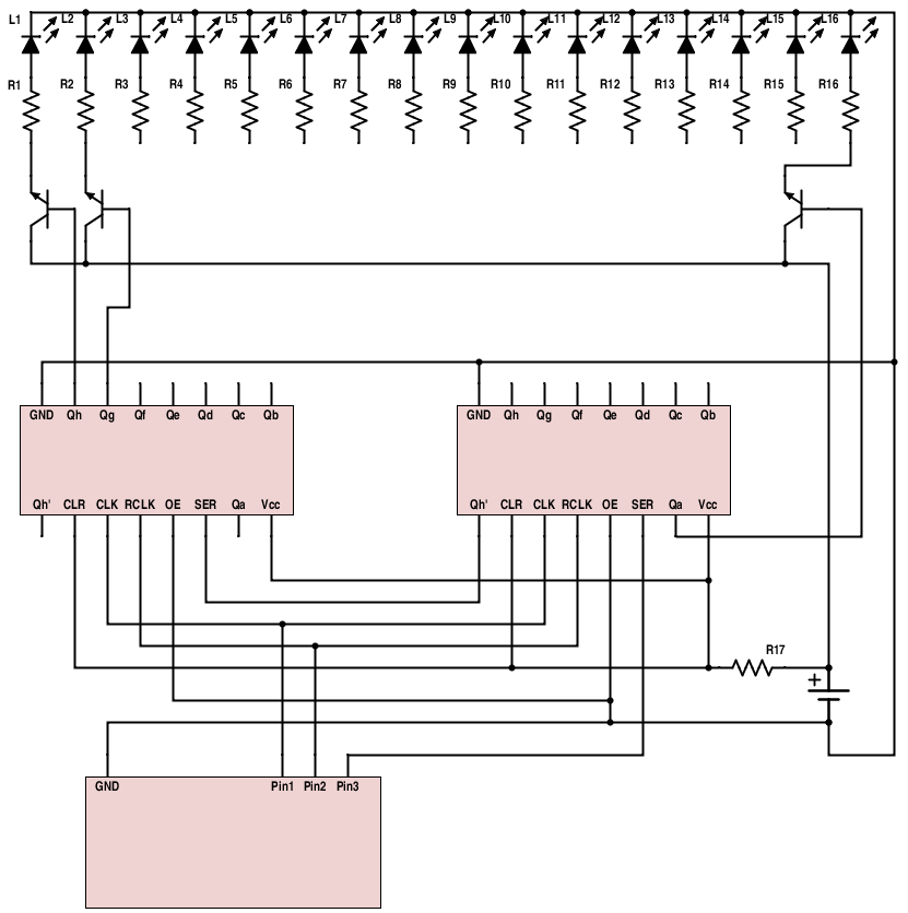
Edit: Here is the adapted schematic, in which the outputs triggers a transistor for each LEDs. I didn't replicate the transistor for every LEDs, but it's assumed that from Qa to Qh on both shift register, it's the same: enter image description here
\$\endgroup\$
11
  • \$\begingroup\$ The microcontroller is not powering the shift register, however the power supply circuit on your netduino circuit board may be, possibly with power sourced from a connected USB host? First improvement you could make is external power, second is turning the LEDs around and driving their cathodes, since low-side drivers are usually more capable. \$\endgroup\$ Commented Nov 10, 2015 at 1:34
  • \$\begingroup\$ You also need to pull the ~OE pins low to properly enable the ouputs. \$\endgroup\$
    – Nedd
    Commented Nov 10, 2015 at 1:39
  • \$\begingroup\$ @Nedd: Yes, that's an error on my schematic. The OE are actually connected to the ground. \$\endgroup\$
    – Tipx
    Commented Nov 10, 2015 at 1:41
  • \$\begingroup\$ @ChrisStratton: I know the microcontroller is not generating power. On the schematic I didn't include the microcontroller's USB port and the computer it's connected to. The DC power source on the schematic is another power source. I'm not sure what you mean by "driving their cathodes". Should I just just flip them over, connecting their anode to the resistor and the cathode to the ground? \$\endgroup\$
    – Tipx
    Commented Nov 10, 2015 at 1:47
  • \$\begingroup\$ Flipping the LEDs is not a good idea. The outputs are positive logic, normally one output goes high at a time. Reversing the LEDs will turn all on but one, and the total current may burn out the chip. The total current for the chip is listed as 70ma. \$\endgroup\$
    – Nedd
    Commented Nov 10, 2015 at 1:51

1 Answer 1

1
\$\begingroup\$

If the microcontroller is running with 3v and the shift registers are at 5v that could be a problem. Per the spec the shift register chips want to see at least a 3.15v min high logic when their supply voltage is at 4.5. (A 5v supply would require even higher logic levels). If you power the shift registers with 3v that should make both compatible. Is there a reason you cannot use the same microcontroller power for the shift register chips?

\$\endgroup\$
6
  • \$\begingroup\$ There is no real reason for me not to power the shift register with the microcontroller, it's the LEDs' power that I don't want to go through the microcontroller not to fry it. The problem is that with my original schematic, even if I didn't power up the 2nd power source, the LEDs would lit up, meaning the current was flowing through the microcontroller, no? \$\endgroup\$
    – Tipx
    Commented Nov 10, 2015 at 2:25
  • \$\begingroup\$ If that's the case you could use a level converter \$\endgroup\$
    – mic
    Commented Nov 10, 2015 at 2:26
  • \$\begingroup\$ As shown the microcontroller is only supplying logic signals to the shift registers, that is not much current at all. If the circuit works as I think you intend there would only be one LED on at a time, even that would only be 14ma at the most, (@ 5v). That can easily be supplied by a small battery or the USB connection. Before connecting the LEDs or any transistors you could test the operation with a logic probe (if the timing is slow) or with a scope at each input/output. Compare the signals at all inputs and outputs to the typical timing diagram in the shift register's data sheet. \$\endgroup\$
    – Nedd
    Commented Nov 10, 2015 at 2:34
  • \$\begingroup\$ If the original circuit had all LEDs lighting up at the same time then you might consider that the LEDs were inserted in reverse to start with. (Another possibility is that the shift register chips are already burned out.) \$\endgroup\$
    – Nedd
    Commented Nov 10, 2015 at 2:40
  • \$\begingroup\$ With the program I wrote, the IO it sends to the shift register can light up anywhere from 0 to 16 LEDs at the same time. I'm testing it with LEDs for the moment, but at one point, I want to control servos with the shift registers. \$\endgroup\$
    – Tipx
    Commented Nov 10, 2015 at 2:47

Your Answer

By clicking “Post Your Answer”, you agree to our terms of service and acknowledge you have read our privacy policy.

Not the answer you're looking for? Browse other questions tagged or ask your own question.