1
\$\begingroup\$

I'm trying to trigger six Panasonic Lumix G7 cameras at once.

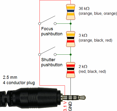
The trigger mechanism uses a four pole 2.5 mm plug, some resistors and two switches. With no switch closed there is 41 kilohms of resistance. To trigger the focus, you reduce that to 5 kilohms. To trigger the photograph or video start you allow 2 kilohms of resistance.

So much I learnt from this great blog post: http://www.robotroom.com/Macro-Photography-2.html

Resistor diagram

Wired this way it triggers a single camera just fine. However, when you add additional cameras to the circuit, it doesn't work anymore. I'm guessing that the resistance is no longer correct, because now the focus trigger does nothing (I think) and a shutter release trigger makes one camera focus.

When I was 11 I was the proud owner of a DSE Funway into Electronics set. I'm afraid I've learnt nothing much since then.

Any way to wire this up so that the resistance is correct for all the cameras? Ideally I could add more than 6 cameras in the future following the same method.

My fall back are independent circuits with a mechanical switch closing them all independently, but 1/100 second accuracy would be a big help here, so I'd love to do it right.

Cheers,

Red

\$\endgroup\$
9
  • \$\begingroup\$ Have you considered fast solid state relays or optoisolators? \$\endgroup\$ Commented Nov 24, 2015 at 10:21
  • \$\begingroup\$ are you using a single set of resistors for all cameras? I think you might need to use a set of resistors for each camera, and then use some active circuitry to drive them all at the same time as alex said. \$\endgroup\$
    – Wesley Lee
    Commented Nov 24, 2015 at 10:26
  • 1
    \$\begingroup\$ The camera is likely to have a resistor internally to form a voltage divider, does what is marked as 3.1 V change as the buttons are pressed? If so it might be worth measuring and updating your post that'd open up a few other options. \$\endgroup\$
    – PeterJ
    Commented Nov 24, 2015 at 10:30
  • \$\begingroup\$ I suspect @PeterJ is spot on here -- knowing what voltages need to be present when the buttons are present helps tremendously here. Also, what's on the other two connector terminals? \$\endgroup\$ Commented Nov 25, 2015 at 1:29
  • \$\begingroup\$ Thanks everyone for the help. I really don't know what the other terminals are used for. Panansonic's wired shutter release (DMW-RS1) doesn't expose any additional functionality than I've already achieved with just the sleeve and the single ring. @PeterJ That's a good question. I just picked up a cheap multi-meter, so I'll try to find out. \$\endgroup\$
    – Redoptick
    Commented Nov 25, 2015 at 10:42

1 Answer 1

1
\$\begingroup\$

ordinary mechanical relays are fast enough to manage 1/1000 second accuracy

have one set of relay cntacts and one set of resistors for each camera. (or two contacts if you needs focus and shutter)

solid-state relays can be non-ideal in interesting ways, but the right one could work too,

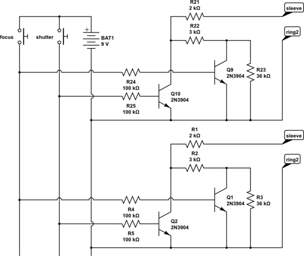
or you could do it in discrete transistors like this;

schematic

simulate this circuit – Schematic created using CircuitLab

(immagine that repeating bit four more times)

\$\endgroup\$
2
  • \$\begingroup\$ Thanks very much! Anyway that I fry one or more cameras if I bungle this? I'm nervous about introducing a power source to the circuit. \$\endgroup\$
    – Redoptick
    Commented Nov 25, 2015 at 10:47
  • \$\begingroup\$ Also, and I really don't know what I'm doing here, when I tried it on CircuitLab in DC test mode it showed 9V at the sleeve and ring. Is that right? \$\endgroup\$
    – Redoptick
    Commented Nov 25, 2015 at 10:50

Your Answer

By clicking “Post Your Answer”, you agree to our terms of service and acknowledge you have read our privacy policy.

Not the answer you're looking for? Browse other questions tagged or ask your own question.