1
\$\begingroup\$

A EDIT: SONY camera release cable is usually designed to short two terminals (+5V EDIT: 3.17V, 0V) when the button is pressed, as shown in the following figure.

Normal camera

These two terminals also lose their voltage difference when a button on the camera body is pressed.

EDIT:

  • When the camera is turned on and the switch is not pressed, a potential difference of 3.18 V is generated, and when the switch is pressed, a potential difference of 4.5 mV is generated.
  • When the camera is turned off and the switch is not pressed, the potential difference is unstable, and when the switch is pressed, the potential difference is 0.0mV.

Therefore, I connected the terminals as follows so that when a button on one camera body is pressed, the shutters on all cameras are released. This actually works.

Current solution

However, I thought that the potential difference between Shutter1 and Shutter2 might cause a current to flow in the opposite direction, which might adversely affect the camera with lower voltage. EDIT: In my situation comparing the two fully charged SONY α7, when two GNDs are shorted with crocodile clips, the potential difference is 0.2 mV and 0.2 µA flows when neither button is pressed, 136.9 µA when camera 1 button is pressed, and 138.6 µA when camera 2 button is pressed.

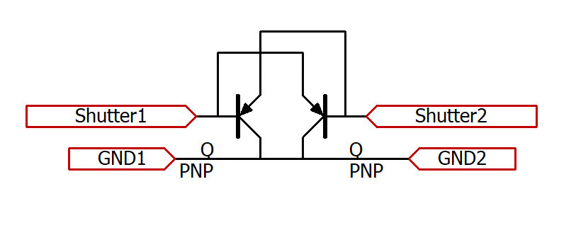
Thus I came up with the following circuit, will this work correctly? I am quite unsure as I am not familiar with electronic circuits.

Circuit

The following solution is available as described here, but I would like to avoid this one because it requires an external button.

With Diode

I modified the question and posted it on photo.stackexchange.com as well following this guideline.

https://photo.stackexchange.com/questions/135365/how-to-make-a-safe-circuit-that-releases-the-shutters-of-multiple-cameras-simult

\$\endgroup\$
7
  • \$\begingroup\$ What potential difference there might be will still be there between the ground lines, which the transistors don't do anything to prevent. \$\endgroup\$
    – MrGerber
    Commented Jul 26 at 15:08
  • \$\begingroup\$ you could ask at photo.stackexchange.com \$\endgroup\$
    – jsotola
    Commented Jul 26 at 17:03
  • \$\begingroup\$ @MrGerber In other words, if the camera is battery powered and there is no potential difference between GND1 and GND2, is this circuit OK? I can't seem to find a way to prevent reverse current at the terminals used for both input and output. \$\endgroup\$
    – mikm
    Commented Jul 27 at 5:12
  • \$\begingroup\$ If both cameras are battery powered and you latch their grounds together, they will have the same potential (unless they're in a strong field with different strengths for different cameras). I would think so. I guess you need to sprinkle some resistors across it. Should be possible to verify with simulator as well \$\endgroup\$
    – MrGerber
    Commented Jul 27 at 7:06
  • 1
    \$\begingroup\$ @jsotola I don't believe so, it's quite niche. But even if they have, it's not topical for Photo-SE. (I'm a mod there, I closed the cross-post over there) \$\endgroup\$
    – scottbb
    Commented Jul 27 at 20:08

2 Answers 2

3
\$\begingroup\$

The small voltage you are measuring when the shutter is triggered is a maintenance/status voltage; it tells the camera to keep the shutter latched in the open position for bulb mode, and that the shutter release is still held open/on for continuous mode. The same behaviors/voltages can be measured using an external switch. And the behaviors are the same for other cameras I have tested, although the voltages may differ a little (e.g. 2.7V/.15mV for Nikon D850).

For small camera arrays the status voltage is small enough to be inconsequential in operation and the diode is not necessary, the voltage will always take the path of least resistance to ground... i.e. reverse current is highly unlikely. In larger arrays the status voltages can accumulate and prevent reliable triggering of cameras on the circuit as they may not see the voltage drop to the required level (depending on circuit design). In that situation diodes and parallel ground connections are necessary. This is also explained in the solution provided here.

However, if you want to be certain you could place a single diode on the signal/shutter wire to make it a one way connection, with camera 1 being the lower voltage. This diagram is more accurate of the design; activating switch 1 will trigger camera 1, activating switch 2 will trigger both cameras (I don't think the ground interconnect is necessary).

enter image description here

\$\endgroup\$
7
  • \$\begingroup\$ The ground interconnect should be necessary \$\endgroup\$
    – Voltage Spike
    Commented Jul 27 at 15:15
  • \$\begingroup\$ Thanks for pointing out that reverse current can be ignored. However for your solution with a diode, I think the voltage difference between cameras is likely to fluctuate depending on factors such as battery level and it would be difficult to use this, or can it be ignored due to the voltage breakdown of the diode? \$\endgroup\$
    – mikm
    Commented Jul 27 at 15:19
  • \$\begingroup\$ @VoltageSpike, why would the interconnect be necessary? The grounds are battery negative and exist at each camera. The voltages (mV) and amperage (uA) should be well within battery tolerances (~7.5V/1.7A for a7 series, ~11V/2-3A for Nikon D8xx series). \$\endgroup\$ Commented Jul 27 at 15:34
  • 1
    \$\begingroup\$ Where is the return current going to come from? You must have two wires to complete a circuit \$\endgroup\$
    – Voltage Spike
    Commented Jul 27 at 17:35
  • 1
    \$\begingroup\$ That's basic circuit stuff \$\endgroup\$
    – Voltage Spike
    Commented Jul 27 at 18:18
2
\$\begingroup\$

You have no reason to suppose that every camera in the world uses 5V. Nor that “shutter” and “ground” are always of the same polarity.

Before you go any further, get yourself half a dozen cameras of each type that you use, in case you blow some of them up in your experiments.

If your cameras’ documentation specifically tells you the voltage and polarity used, does it also tell you what voltage on the input means “button pressed”? A mechanical switch can pull an input down to 0V. A conducting transistor never can. This may or may not make a difference. The camera manufacturer may know or may have forgotten; and may or may not tell you.

Given the expense of camera equipment and given the way your design is depending on guesses about how you think cameras ought to work - do reconsider the whole approach. A separate button which controls reed relays, a separate one for each camera, is guaranteed to work and guaranteed to be safe without relying on any undocumented features of cameras.

\$\endgroup\$
1
  • \$\begingroup\$ 1. Yes you are right, I corrected the question because the voltage was incorrect. 2. So far the camera is not broken. 3. There are very few cases where the manufacturer clarifies the specifications of the release cable. This should have been clearly stated. I do not know how the switch inside the camera is related to the connector. 4. Yes, thanks for the warning. \$\endgroup\$
    – mikm
    Commented Jul 27 at 9:33

Your Answer

By clicking “Post Your Answer”, you agree to our terms of service and acknowledge you have read our privacy policy.

Not the answer you're looking for? Browse other questions tagged or ask your own question.