3
\$\begingroup\$

Is there a sensor that can sense whenever rotating wheel pass the ground? Like when mounted on a bicycle wheel rims, but without anything mounted on a bicycle frame - only mounting on a wheel it self is allowed.

Sensor does not have to be much accurate, but must be fast to detect ground passed at up to 3000rpm (or at least 1000rpm). I would like to connect it to a MCU also mounted on a rotating wheel.

\$\endgroup\$
7
  • 3
    \$\begingroup\$ Do you really mean "detects when wheel passes ground"? or instead "when a given point on the wheel is at it's lowest point IF the bike is on a flat hozizontal surface. This is important as detecting wheel position and detecting ground are two different sorts of problem. Tell us what you REALLY want to do and we'll tell you how to do it :-). \$\endgroup\$
    – Russell McMahon
    Commented Oct 10, 2011 at 15:53
  • 4
    \$\begingroup\$ What is the wheel on? Is this a vehicle? Battle bot, tank, car, motorbike, ... ? If it is a motorcyle and you can "loft the front wheel and you want to know when ground comes near again, we need to know. If this is s rally car, moon lander, ... we need t know. \$\endgroup\$
    – Russell McMahon
    Commented Oct 10, 2011 at 16:00
  • 1
    \$\begingroup\$ The wheel is on the car. I can not mount magnet or something reflective on the car frame to use hall effect sensor, IR and similar. Thank you for your input. \$\endgroup\$
    – avra
    Commented Oct 12, 2011 at 6:09
  • \$\begingroup\$ Magnet need not be on frame. if this is a conventional wheel it has a stub axle and bearings and a backing plate etc. The clearance between still and rotating parts is very small - mm. But eg magnet could be 10mm - 20mm away on a backing plate etc. \$\endgroup\$
    – Russell McMahon
    Commented Oct 12, 2011 at 8:20
  • \$\begingroup\$ @avra Is there a specific reason you can't mount the device on the rim and use a counter weight to keep the wheel balanced? If so could you instead run a sensor from the hub to the rim? It might help to reconsider the mechanics of your situation before focusing so much on the electronics. \$\endgroup\$
    – snoopen
    Commented Oct 12, 2011 at 22:44

3 Answers 3

3
\$\begingroup\$

You already tagged it "accelerometer", and that may be the way to go. If the wheel doesn't rotate the sensor will see +1g in a certain position , and -1g in the opposite position. Rotating will fluctuate the reading between those two, though it must be noted that centrifugal force will add a fixed acceleration, especially when rotating as fast as you plan to. The total acceleration should still show a sine wave, once per rotation, superposed on a constant level (constant if the rotation speed is constant).

\$\endgroup\$
5
  • \$\begingroup\$ At up to 1000 rpm I need more then 10 Hz digital gyro. Do you know of some super fast one? Can +1g and -1g be measured at 1000 rpm with strong centripetal force? Can constant centripetal force be eliminated by some math to extract directional vector? Do you have some link? Thank you very much for your valuable input. \$\endgroup\$
    – avra
    Commented Oct 12, 2011 at 7:23
  • 1
    \$\begingroup\$ @avra - a gyro won't detect the variation due to gravitation, that's what an accelerometer does. At the given speed the acceleration may be greater than the accelerometer's range, but this can be taken care of by placing the accelerometer at an angle, reducing it's sensitivity. You should still see the acceleration due to gravity as a sine superposed to the constant level due to the rotation. \$\endgroup\$
    – stevenvh
    Commented Oct 12, 2011 at 7:44
  • 1
    \$\begingroup\$ 1000 rpm => roughly 10 hz. Given that the wheel spin is essentially constrained to one axis, you should be able to filter pick out peaks/valleys in the accelerometer output to detect when you're pointed more toward the ground or the sky. The bigger worry is the maximum load the accelerometer will support. There are a bunch of analog accelerometer's out there that should be able to give you closer to 100 or even 1kHz response, depending on your noise tolerance. \$\endgroup\$
    – Toybuilder
    Commented Oct 12, 2011 at 22:59
  • \$\begingroup\$ @stevenh: Sine should not be a problem. I know how to extract needed data from it. Thanks for nice tips. \$\endgroup\$
    – avra
    Commented Oct 13, 2011 at 14:22
  • \$\begingroup\$ @toybuilder: Thank for the info about 100-1000Hz accelerometers. I was not aware of their existance. With those speeds I think I can even handle properly distorsion data when car is breaking. \$\endgroup\$
    – avra
    Commented Oct 13, 2011 at 14:26
7
\$\begingroup\$

There are a number of options. A few include:

  • Capacitive sensor - detects ground coming and going and allows a maximum to be detected.

  • As the ground is at a fixed angle to the wheel support structure, detecting when a point goes past a swing arm or fork or whatever will allow you to determine when another point is near the ground.
    Sensor can then be inductive, magnetic etc.

  • Optical sensor can detect ground proximity - either passive using daylight or by detecting eg an infrared beam.

  • Simple RADAR can do this well enough - this can be as simple as a few transistors.

  • Acoustic (usually ultrasonic) position detection can do this.

  • Magnetic detector determines wheel position using earth's magnetic field OR field of an attached magnet.

  • Hall sensor, fluxgate and similar measure field strength.
    GMR. AMR and similar measure field angle.

  • Two (or 3) orthogonal coils can detect position in space relative to a field.

  • Gyroscope (Mems)

More ...

Tell us what you REALLY want to do and we'll tell you how to do it :-).

_______________________-

Accelerometer:

Steven has mentioned accelerometer. I thought of this but left it out. These are relatively cheap and are readily available. But if this is on a vehicle (and that wheel is turning at a considerable speed for a vehicle if it is a normal wheel size) then accelerations due to turning and acceleration in various planes will make the job harder. You will still get a cyclic gravity variation of +/- 1g but it will be added to centripetal acceleration and turning, suspension and impact force effects. It MAY be the best solution, but some other that is not so affected by the vehicle dynamics is liable to be better.


RADAR

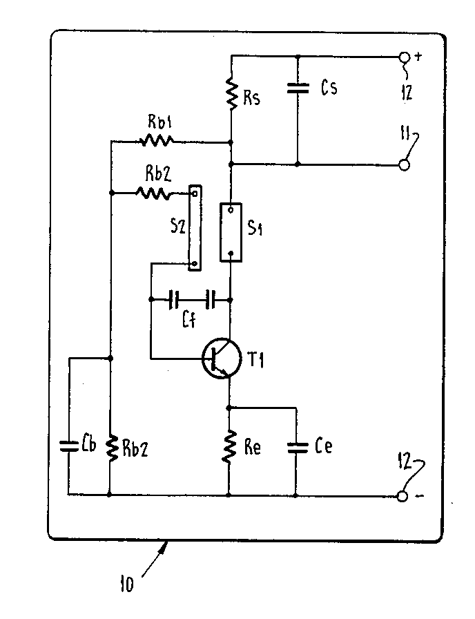
A Doppler RADAR may be implemented by using a self oscillating transistor or push pull pair at VHY or UHF to mix return signal with outgoing signal and return the difference frequency, which is the Doppler signal. The oscillator needs to be short term stable enough for the Doppler frequency difference to be detectable but can be less stable long term.

Here's a curcuit from someone pushing this to the limit. That's from US patent 4672379 - no guarantee of practicality as shown. I recall a hobby magazine in the last 20 years or so doing a self oscillating psuhpull pair with perhaps a diode detector. And Silicon Chip magazine (13 November 2006) published a RADAR speed gun project.
enter image description here

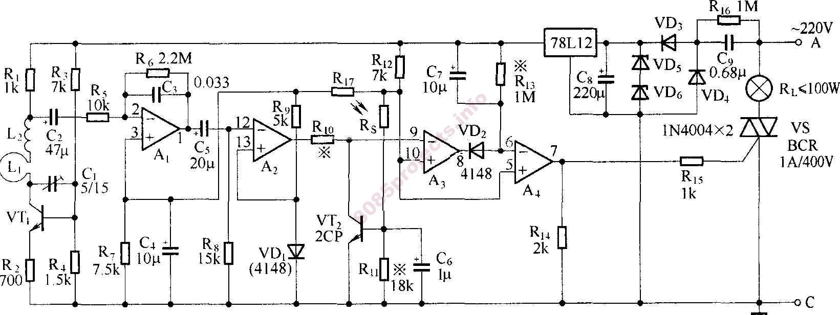
Here's a RADAR operated lamp circuit !
VT1 oscillates and receives. C couples the low frequency Doppler difference signal to amplifiers A1, buffered by A2, magic by A3 and rectified by A2 A3 then it is rectified by
enter image description here


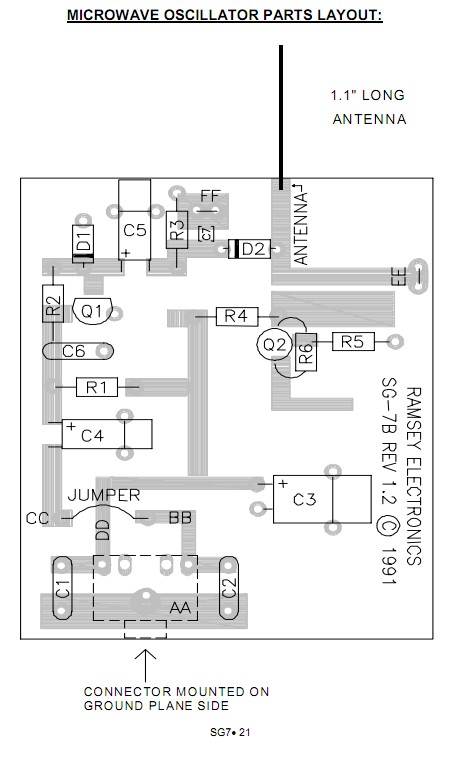
Here is an excellent assembly manual for Ramsey SG7 personal speed radar which does NOT have a circuit diagram but provides enough visual detail of the RF board for the very simple circuit of the RF transceiver and mixer to be easily traced out. Viz -
enter image description here


It would be nice not to have to play "guess 1000 questions" and just have the real spec explained instead of sneaking up on it slowly, as we are doing now. If this is for a "hub odometer" type arrangement whose main aim is to measure wheel RPM then an easy and effective way is to have an internal "bob weight" which hangs down internally and does not rotate when the wheel does. The electronics then sense it going past a point on the PCB etc. This needs a mechanical bearing but this is very easy to do, easy to design and can be very long life indeed. The hub-odometer industry churns these out by the millions. This is THE easiest high output level simple arrangement if you can tolerate the bearing requirement.

People have made electronic rotation sensing hubodometers for decades. Many of the methods mentioned by me and others could be made to work. A cyclical waveform that changes within cerain rate boundarioes can be extracted from the noise. eg an accelerometer can be arranged to be orthogonal (at 90 degrees) to "centrifugal" acceleration and will see cyclical gravity variation. Radar should be easy enough [tm] Note it may want to see wheel arches etc depending on where it is pointed.

You MAY be able to do a differential capacitance sensor - or inductance. With two sensing "ends" at 180 degrees one will see road while other is seeing sky so signal will vary between two states with A-B at one monet and B-A 180 degres later. Even very low level signals can be extracted by autocorrelation or other means.

\$\endgroup\$
7
  • 1
    \$\begingroup\$ OK - who downvoted this without saying why? It's hard to imagine what aspect deserves that - but that's all the more reason to say why. (Wrong color? Wrong perfume? rives on the wrong side of road? ... ?) \$\endgroup\$
    – Russell McMahon
    Commented Oct 11, 2011 at 11:15
  • \$\begingroup\$ 1) The way I understand capacitive sensor it needs time to detect near by object, and I don't have much at 1-3000rpm. Please provide some sensor link if you think this still might be an option. 2) How can I use magnetic or inductive sensor if nothing can be mounted on the wheel support structure? The only place where whole electronics can be mounted is in the center hole of alloy rim (to keep the wheel balanced). 3) I was already thinking about directed light sensor that should sense sky light but it will have problems in the night. Do you maybe have some other idea? \$\endgroup\$
    – avra
    Commented Oct 12, 2011 at 6:20
  • \$\begingroup\$ 4) I don't know any affordable radar that could do it. 5) I was already thinking about directed ultrasonic sensor that could detect reflection from the ground, but I have serious concerns that it will also have false detection when pointed to the sky because of car reflection. Could I be wrong? 6) I was already thinking about compass, but I couldn't find one with 100+ Hz and I don't know how to extract north direction from constantly changing vector that rotates in 2 planes. Is there some link or hint about this? \$\endgroup\$
    – avra
    Commented Oct 12, 2011 at 6:37
  • \$\begingroup\$ 7) Hall effect sensor needs magnet mounted outside of the wheel, which is not an option. I looked at wiki pages for fluxgate and GMR/AMR but I don't get an idea how to use them. Can it be used up to 3000rpm? A link to a specific product would be very helpful. 8) Is there some sensor that uses coils method you mentioned for 3D positioning? 9) Digital gyro with 10Hz is too slow, and I haven't seen any faster sensor. Can constant centripetal force be eliminated by some math to extract vector? I am not aware of such calculation. Thank you very much for your valuable input. \$\endgroup\$
    – avra
    Commented Oct 12, 2011 at 7:16
  • \$\begingroup\$ Correction: After recalculation I saw that max usable rotation is not 3000 rpm but about 1000 rpm. Sorry about this. \$\endgroup\$
    – avra
    Commented Oct 12, 2011 at 7:25
2
\$\begingroup\$

Taking a somewhat far-left field approach, can you mount this on the inside of the tire? Maybe a piezo-electric effect of a tire under deflection when it's in contact with the ground can be used. :)

\$\endgroup\$
1
  • \$\begingroup\$ Unfortunately no. Only in the center of the wheel. However nice thought. Thank you for your input. \$\endgroup\$
    – avra
    Commented Oct 13, 2011 at 14:09

Your Answer

By clicking “Post Your Answer”, you agree to our terms of service and acknowledge you have read our privacy policy.

Not the answer you're looking for? Browse other questions tagged or ask your own question.