2
\$\begingroup\$

Goodmorning all,

Here my very first question so I may be asking something that is may be already answerd but I couldn't find,

My question is : How is current limiting achieved in modern IGBT based welding equipment? I do have a DC TIG welder myself and I am just curious how to achieve a max current setting from let's say a very wide range between 5-180 Amps?

I have googled quite a lot but I can't find anything that is helping me understanding this aspect of power electronics

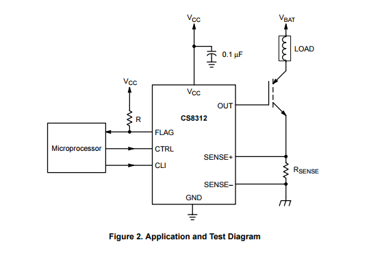
The only thing that gets close to it is the CS8312 that controls the gate of the IGBT for a specific max current through the IGBT.

Any help suggestion is appriciated!

Cheers

\$\endgroup\$

1 Answer 1

1
\$\begingroup\$

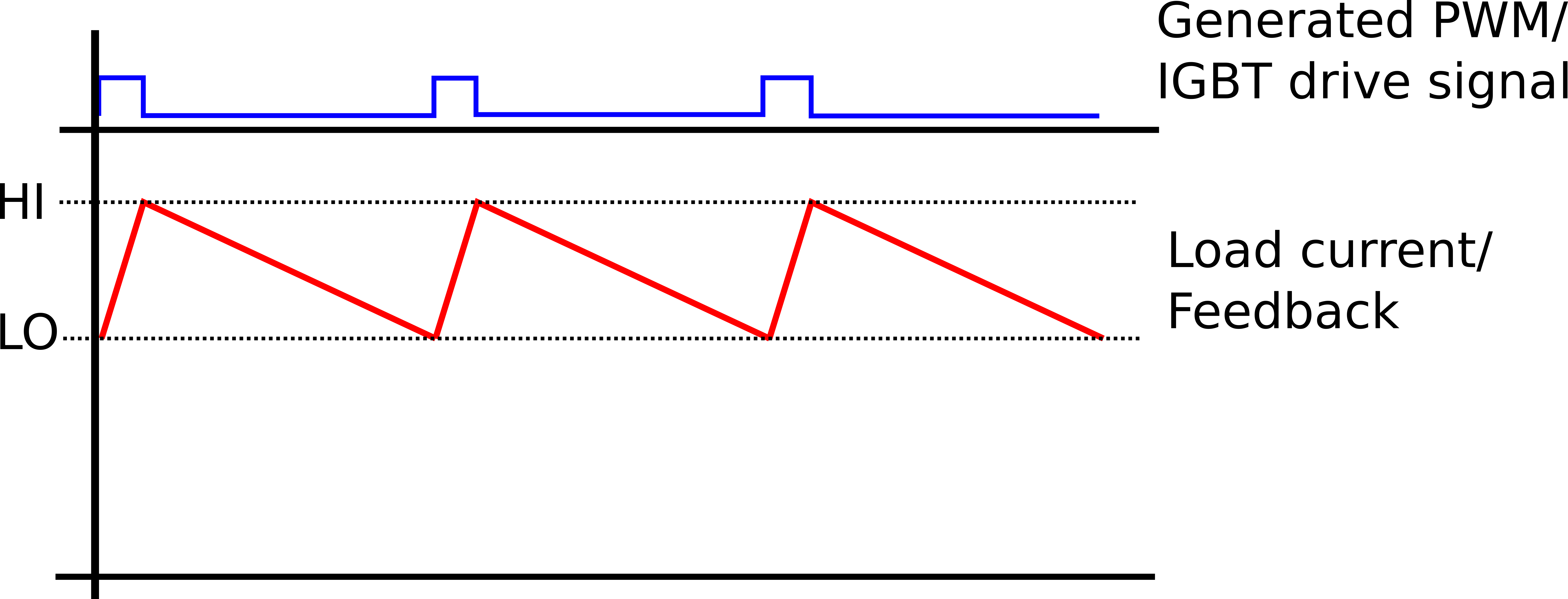
With an inductive load and PWM.

IGBT's are optimised to be Discrete ON or OFF devices and do not have a linear/active region like MOSFET's and BJT's.

The CS8312 shows an example setup with an inductive load and a sense resistor.

This particular chip works by increasing the threshold by 45%

Changing the CLI pin from a logic low to a logic high increases the FLAG turn on voltage by approximately 45% and the regulation sense voltage by approximately 39% respectively.

Other methods are via simple comparator for hysteresis control or PI controller to then generate a PWM signal that is indirectly used to drive the IGBT

enter image description here

enter image description here

\$\endgroup\$
4
  • \$\begingroup\$ So it means that the effective or dynamic current == (Ton/(Ton+Toff))*Imax? You would also expect more like a square wave Usense I guess? \$\endgroup\$ Commented Dec 22, 2015 at 16:02
  • \$\begingroup\$ not quite for average current as there is the slope to consider. For this topology with the current not in the freewheel path, Yes Usense would be "square wave" & depending on how much inductance, there should be a slope. NOTE: it is assumed the freewheel diode is part of the load. \$\endgroup\$
    – user16222
    Commented Dec 22, 2015 at 16:41
  • \$\begingroup\$ I_lo + 0.5*(dITon^2 + dIToff^2 )/(Ton + Toff) ... Where I_lo = low current, dI is the change in I (T_hi - Tlo) \$\endgroup\$
    – user16222
    Commented Dec 22, 2015 at 16:47
  • \$\begingroup\$ The inductance load causes also the ramp up slope's angle of the upgoing Load current when the IGBT is on and also the ramp down angle/slope of the receding Load current or to be more precise : the current through the load which has a clear inductance component \$\endgroup\$ Commented Dec 22, 2015 at 16:56

Your Answer

By clicking “Post Your Answer”, you agree to our terms of service and acknowledge you have read our privacy policy.

Not the answer you're looking for? Browse other questions tagged or ask your own question.