2
\$\begingroup\$

I typically put a TVS diode on all of my power rails as standard practice to protect against ESD events. I'm using an FPGA in a design for the first time and I'm finding that I can't get a TVS with a 1.2V reverse standoff voltage to protect the FPGA core voltage. The only close options I could find were these two:

1.0V holdoff (too low?), 1.5V breakdown: https://www.digikey.com/product-detail/en/VESD01-02V-G-08/VESD01-02V-G-08CT-ND/2658775

1.5V holdoff, 4.8V breakdown (probably useless given the 1.32V absolute max voltage on the FPGA?): https://www.digikey.com/product-detail/en/DF2S5.1ASL,L3F/DF2S5.1ASLL3FCT-ND/5415965

Can I get away with using the 1.0V holdoff part? Is there a better way to protect a power rail at this low of a voltage?

\$\endgroup\$
4
  • \$\begingroup\$ Power rails are usually low impedance enough that a TVS is unnecessary. Keep them on your IO pins. \$\endgroup\$
    – Matt Young
    Commented Dec 23, 2015 at 16:24
  • \$\begingroup\$ What ESD events are you expecting? Shouldn't your low voltage regulator be placed up-close to the FPGA minimizing the opportunity of ESD events? \$\endgroup\$
    – Andy aka
    Commented Dec 23, 2015 at 16:35
  • 2
    \$\begingroup\$ @Andyaka It's for a test fixture to production QC test other boards so I'm expecting it to be handled quite a bit during operation (board-mount push buttons etc). \$\endgroup\$
    – Joe Baker
    Commented Dec 23, 2015 at 16:43
  • 1
    \$\begingroup\$ 1.2 V-rated pins is a bit low to expose to handling in a production environment. Can you add series protection resistors (100 ohm) ?, then a 3.3 V zener 'outside' the R ? \$\endgroup\$
    – jp314
    Commented Dec 23, 2015 at 16:53

2 Answers 2

3
\$\begingroup\$

Here's the device: -

enter image description here

On the basis of this table I'd say you will be fine operating it on a 1.2 volt supply - it's only going to take typically 1.5 mA on a 1.5 volt supply so with a 1.2 volt supply, current should be hardly worth bothering about.

Unfortunately the data sheet appears to have an omission - figure 1 does not appear to be included.

Is there a better way to protect a power rail at this low of a voltage?

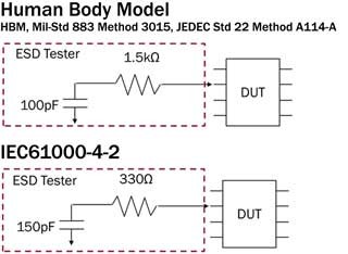
There probably is and it might be a crowbar protector. You have to consider the effects of distributed capacitance on your power rail and what sort of ESD event your board actually receives. You should be able to make a basic LTSpice model of both the event (human body model) and board capacitance and distributed inductance. Human body model usually falls into to groups: -
enter image description here

I can't tell you which to choose as typical for your ESD event, you have to decide that but, when you do you simulate the cap being charged to 4kV or 8kV (your research is needed here), do a simulation of this connecting to your distributed capacitance (seperated by PCB inductance) and see what peak voltage you get.

You are looking to either not have a voltage rise that is going to damage anything or, if this is not possible, you are looking for the rate of rise to be slow enough so that a crowbar circuit can begin to work (in conjunction with your TVS).

You are likely to have a 3V3 rail or greater so something that monitors the rail and kicks in above 2V to turn on a MOSFET (or SCR) to crowbar the supply is an option worth considering.

\$\endgroup\$
3
\$\begingroup\$

You're right that you won't find a conventional ESD/TVS solution at these low-voltages. What I've done in the past is use an "analog" MOSFET like that ALD11193 which presents a very, very precise turn-on voltage to trigger a high-current crowbar MOSFET. When the precision MOSFET is triggered, it will then trigger the higher power, conventional transistor and crowbar the rail to GND.

This will protect against power rail transients (filter the gate input accordingly), but won't be enough for ESD protection; as others have said, you may want to ensure that those I/Os pass through level-shifters or series resistors.

Here is a link to an app note about the ALD parts: http://www.aldinc.com/pdf/VoltageClampCircuits.pdf

\$\endgroup\$

Your Answer

By clicking “Post Your Answer”, you agree to our terms of service and acknowledge you have read our privacy policy.

Not the answer you're looking for? Browse other questions tagged or ask your own question.