2
\$\begingroup\$

I can make an LED glow very dimly in all 4 following circuits. The voltage source in the circuits is the output of an AC to DC converter fed into a breadboard. Also, one end of the voltage source is always floating, as shown on the schematics.
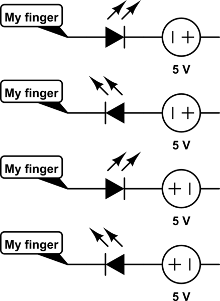
schematic

simulate this circuit – Schematic created using CircuitLab

What is the physics behind this? I understand that there occurs a potential difference between me and positive AND me and negative terminals of my power supply but I don't know how and why this happens. Also I understand that depending of the circuit, my electrical potential becomes:

  1. Higher than the negative terminal
  2. Lower than the negative terminal
  3. Higher than the positive terminal
  4. Lower than the positive terminal

Since the LED glows in all 4 configurations. How is this happening?

\$\endgroup\$
3
  • \$\begingroup\$ Your voltage sources appear not to be connected to anything on the right hand side. Details of this and the size of conductors and localized earths and localized AC wiring in walls/floors is fundamental to answering this. \$\endgroup\$
    – Andy aka
    Commented Jan 6, 2016 at 8:37
  • \$\begingroup\$ @Andyaka I have edited the question. Do I need to add further information? \$\endgroup\$
    – Utku
    Commented Jan 6, 2016 at 8:47
  • \$\begingroup\$ What is the AC -> DC Converter? Unless it has a transformer inside it, then there is actually a path to ground which is not shown on your diagram. \$\endgroup\$
    – Mark Ch
    Commented Jan 6, 2016 at 10:51

1 Answer 1

3
\$\begingroup\$

If the situation was exactly like you sketched, then it cannot be explained that the LED lights up !

So something else is going on

Your power supply of 5 V is also capacitively coupled to the mains voltage and this causes a voltage between you and the 5 V supply.

All power supplies have this capacitive coupling caused by the transformer inside it and a small value capacitor between mains and output to prevent emissions of high frequency signals. The total capacitance will usually be less than 1 nF but that is enough to light up a sensitive LED.

Try this again with a battery and you'll see the LED does not light up.

\$\endgroup\$
4
  • \$\begingroup\$ "Your power supply of 5 V is also capacitively coupled to the mains voltage and this causes a voltage between you and the 5 V." Then this is the reason the LED lights up right? \$\endgroup\$
    – Utku
    Commented Jan 6, 2016 at 8:51
  • \$\begingroup\$ Yes, it causes a small (AC) current to flow between your body and mains. Instead of a LED you could also use a neon-lightbulb, these light at very small currents as well. For electricians there are tester screwdrivers with a build-in light to safely test if a line is live. These testers use a neon light and a resistor to limit the current (so the electrician is not electrocuted). \$\endgroup\$ Commented Jan 6, 2016 at 10:27
  • \$\begingroup\$ This is a similar way of saying that your finger is providing a path to charge/discharge (depending on the direction of the LED) the capacitor in the ac -> dc converter for half the cycle. \$\endgroup\$
    – Mark Ch
    Commented Jan 6, 2016 at 10:48
  • \$\begingroup\$ Not completely, the voltage can be quite high (otherwise a neon light would not light up) so the LED will not rectify as it cannot block the high voltage, it will just conduct. But since the path has a high resistance and is capacitively coupled the current will be small so the LED will not be damaged. There is no relation to the decoupling cap in the AC-to-DC (diode bridge) as these will be low-ohmic when operating. Study the schematic of a modern switched mains adapter and it will be clear what is happening. \$\endgroup\$ Commented Jan 6, 2016 at 11:17

Your Answer

By clicking “Post Your Answer”, you agree to our terms of service and acknowledge you have read our privacy policy.

Not the answer you're looking for? Browse other questions tagged or ask your own question.