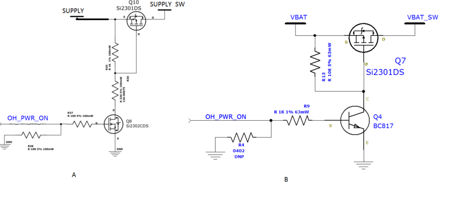
The drawings below are controlled power switches. I already tried them both and seems to work. Can someone tell me please which is better to use? Any advantage and disadvantage.
-
\$\begingroup\$ Hardly any to speak of. \$\endgroup\$– DanielCommented Jan 14, 2016 at 6:52
-
\$\begingroup\$ Maybe you have a specific application? If not, please attempt to indicate what you have found out so far? \$\endgroup\$– Andy akaCommented Jan 14, 2016 at 8:29
-
\$\begingroup\$ the one on the right wastes less power, but that's mostly due to the resistors you chose, and could be reversed easily. \$\endgroup\$– Jasen Слава УкраїніCommented Jan 14, 2016 at 9:07
-
\$\begingroup\$ How much current can the left one handle? \$\endgroup\$– Scott WoodCommented Aug 9, 2018 at 16:12
2 Answers
You're trying to compare a BJT and MOSFET in switching application.
First you need to define your application (power, frequency, current, voltage...etc), then you compare the two transistors according to the datasheet of each one.
Bipolar transistors are more adapted to a general purpose switching applications, for high power MOSFET are more suitable because they are faster than BJT. for the MOSFET see the switching parameters in the datasheet. BJT loss current when they are used in high power applications.
Both circuits use the same MOSFET (Q10 and Q7) for switching power, so the performance of the 2 circuits, in terms of switching power, will be identical.
The difference between the 2 circuits is that the left circuit uses a MOSFET Q8 to control Q10, whereas the right circuit uses a bipolar transistor Q4 to control Q7. If you are controlling these circuits from a microcontroller running from 3.3V then the right circuit will load the micro's output pin with about 2.6mA, whereas the left circuit will load it with about 330uA. In fact, if you increase R38 to 100K you can reduce the load down to 33uA.
Personally I'd go with the left hand side circuit.

