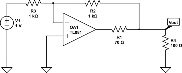
The following circuit is a simple voltage regulator. The Vout is maintained at -1V, however the opamp in the circuit has a non-zero output impedance. This is represented by the resistor R1.

simulate this circuit – Schematic created using CircuitLab
I have been told that the following procedure will allow me to measure the output impedance of this circuit.
- Remove r4 and measure the open circuit voltage
- Measure the voltage with r4 (which has been chosen to be close to the expected output impedance)
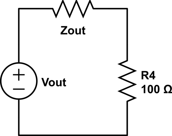
- Now the circuit is modelled as a voltage divider and the output impedance is found

Where Vout is the open circuit voltage measured above, and the second voltage is across R4.
The expectation is that adding the resistor will cause a slight decrease in the output voltage. Now, assuming the circuit was accurately represented by the above circuit, this would all make perfect sense. However, as far as I can tell the feedback loop ensures that the output voltage is at -1V, unless the resistance is so low as to cause the output to be clipped. (The person describing the measurement ensures that clipping doesn't happen by varying V1 and making sure the output changes linearly).
My problem is that if the output voltage shouldn't change at all (it is a voltage regulator after all), so that the result will always be close to 0 Ohms. Again, we are assuming the R4 is not so low that that clipping occurs. The person describing the measurement however expects to find around 70 Ohms, and blames the much lower recorded values (2 Ohms) on the variation of the opamps.
So is there any reason that this measurement would get an answer other than 0 Ohms?
