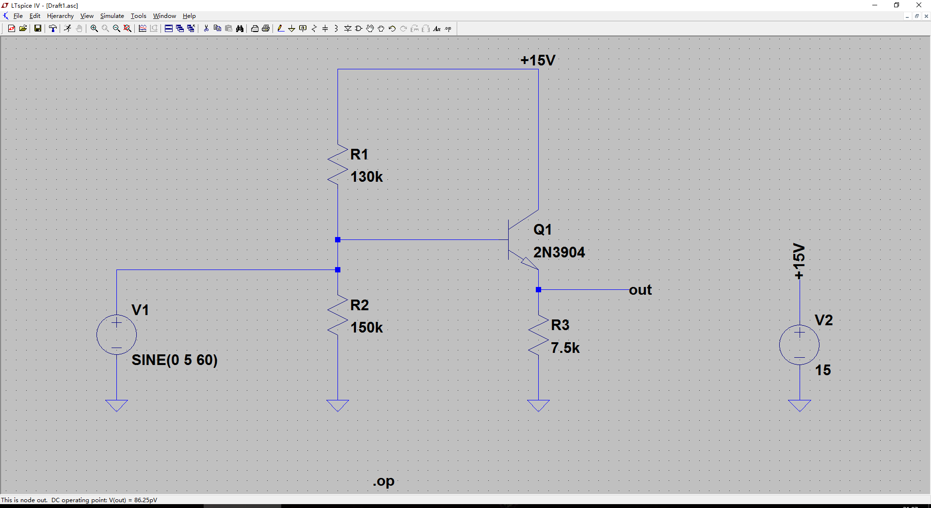
I'm trying to simulate a biased emitter follower in LTspice. The dc operating point seems to be wrong once I used a DC coupled sine input signal(zero offset, 5V amplitude, 60Hz), it is almost 0V at emitter follower's output. Once I place a capacitor between sine input and voltage divider(make the input signal ac coupled) the dc operating point makes sense, it is about 7.5V, half the supply voltage. I think there is no difference for a zero offset sine input signal to be ac or dc coupled. So why a DC coupled sine input signal will make my biased emitter follower looks like unbiased in LTspice? Is it just simulation behavior or in real life it actually behaves like this?

-
\$\begingroup\$ Remove the bias resistors and set the desirable DC offset at the sine wave oscillator. \$\endgroup\$– ilkhdCommented Mar 23, 2016 at 6:46
3 Answers
The sine wave source V1 is an ideal voltage source, so its internal impedance (resistance) is zero! Therefore there is a "short circuit" from the base of Q1 to ground (R2 is shorted) from the bias (operating point) point of view. This is not the simulation behaviour but reality.
-
\$\begingroup\$ I try to make the signal source to have 50Ohm output impedance, but it seems the same... edit: Sorry I think I got your idea wrong. So I should have my signal source ac coupled... \$\endgroup\$– iouzzrCommented Mar 22, 2016 at 13:49
-
\$\begingroup\$ OK, then the operating point will change as if you connected 50Ohm in parallel to 150kOhm (R2) => R2' = 49.98Ohm. The base voltage will be ~ 15V* 50/130050 = 5.77mV. Still not much... \$\endgroup\$ Commented Mar 22, 2016 at 13:55
The DC coupled source will force the bias point (average DC value at the base) to be zero. It's a voltage source so expect no less - you always get out of it what it says on the tin and if the source has no dc offset then the base isn't biased except when the peak of the AC part of the signal rises high enough to momentarily turn the transistor on.
-
1\$\begingroup\$ So it always need an ac coupled signal for the resistor divider to bias the emittor follower? \$\endgroup\$– iouzzrCommented Mar 22, 2016 at 13:48
-
\$\begingroup\$ That is correct. Add a coupling capacitor between V1 and the bias point \$\endgroup\$ Commented Mar 22, 2016 at 15:23
You are shorting out the bias network with your sine wave source. If that represents the way your real world circuit must be connected, the simplest (but not the only) answer is AC coupling via a capacitor.
If the sine wave source can be connected more flexibly (neither terminal is grounded) you can connect it between the bias network and Q1 base, i.e. in series with the bias instead of in parallel. This works if both ends of the source are floating, e.g. it is the secondary of a transformer.
