0
\$\begingroup\$

I am trying to design a IIR lowpass filter. The purpose of this filter is to get pure DC from noises.

  1. The sampling rate is: 125Hz.
  2. The bandwidth of the filter: 0.2Hz.

I designed the filter with Matlab:

[b,a] = ellip(3,0.001,60,0.001);
freqz(b,a);
figure(2)
out = filter(b,a,ones(1,2000));
plot(out)

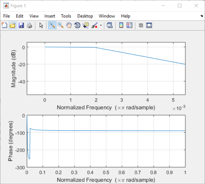
The frequency response: at 0.3Hz is -20dB, which is good for me. enter image description here
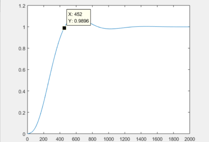
The step response: enter image description here

The coefficients:

a = [1.000000000000000 -2.984668175804313 2.969460975930567 -0.984792292477895];

b = 1.0e-04 *[0.750233362790290 -0.747695120994728 -0.747695120994729 0.750233362790290];

My questions

  1. From the step response, it seems that the 452th data is close to 1. Can I say that I have to wait for 451 data to get a desired DC value? By desired, I do not care much about the gain ripple on DC, meaning that it is fine for me if DC has a small gain(0.9-1.1) on it.

  2. The filter coefficients seem to be pretty small, especially the b part. Can I implement the filter successfully on a Cortex-M4, which is a 32 bit MCU with FPU?

\$\endgroup\$
4
  • 1
    \$\begingroup\$ That is a lot of decimal places... \$\endgroup\$
    – Tyler
    Commented Mar 24, 2016 at 14:16
  • \$\begingroup\$ There are float types supported in Cortex-M4. Even double, I think. \$\endgroup\$ Commented Mar 24, 2016 at 14:17
  • \$\begingroup\$ How would you know the start time to wait, if this is all realtime? If you want to extract noise from system, there is no such time period that you can know "a priori", like from now and after x-samples I get the real value. \$\endgroup\$ Commented Mar 24, 2016 at 15:19
  • \$\begingroup\$ @MarkoBuršič great question! Because I will record the response of the system after a known stimulus. The stimulus is generated by me at a specific known time. \$\endgroup\$ Commented Mar 24, 2016 at 15:21

1 Answer 1

1
\$\begingroup\$

Try grpdelay(b,a,1e6)

This will plot the group delay of the filter at various frequencies and I get about around 240 to 350 samples for 'low' frequencies.

Yes, 32 bit should be sufficient.

\$\endgroup\$
2
  • \$\begingroup\$ Thanks for your reply. At 350th data, it shows 0.768. Shall I compensate it with gain of 1/0.768? Or can I actually use, say the 100th data, which is 0.06 and compensate with 1/0.06? \$\endgroup\$ Commented Mar 24, 2016 at 14:27
  • 1
    \$\begingroup\$ No problem! Actually no, I would not try to do that. Note that these numbers below 1 are actually artifacts of the change, and changes are what you are trying to filter out. So in steady-state, i.e. measuring something genuinely DC, I would use exactly what the filter outputs. I suppose, if you know for certain that a change occurred at some point, and you want a really accurate measurement of that, you might weight 4 or 5 time constants (group delays) and measure out at the 1500th or so. \$\endgroup\$
    – MikeP
    Commented Mar 24, 2016 at 14:34

Your Answer

By clicking “Post Your Answer”, you agree to our terms of service and acknowledge you have read our privacy policy.

Not the answer you're looking for? Browse other questions tagged or ask your own question.