3
\$\begingroup\$

According to Steven W. Smith, in his book: The Scientist and Engineer's Guide to Digital Signal Processing, when designing a digital filter, "Good performance in the time domain results in poor performance in the frequency domain, and vice versa", and one needs to find a good trade-off for one's needs; and from what I understood, bad performance in the time domain means that the signal's waveform will be altered, meaning it will be somehow distorted after going through the filter. Additionally, the filter's step response is of the most importance when it comes to achieving good performance in the time domain. http://www.dspguide.com/CH14.PDF

So, after I designed two filters with matlab that aim to rid a signal from the electromagnetic interference (lowpass), and the DC component (highpass), and thinking that linear phase filters preserve the shape of the signal because all frequency components are shifted equally, so I went with the FIR filter option, and by using the function fircls1 that allows for defining the ripple levels in the passband and stopband, with the former being the concern for preserving the amplitude levels of the different frequency components, I thought I am getting the best possible "time domain" response, and the shape of the waveform in the time domain is as intact as could possibly be, moreover, I used an adequate number of points in the filter kernal to get the roll-off I desired, and after all that I came across that phrase in the first paragraph, this time I paid more attention and said let's have a look at the step response of the filter. Before I was solely concerned about the frequency response, ripple and stopband attenuation, etc.

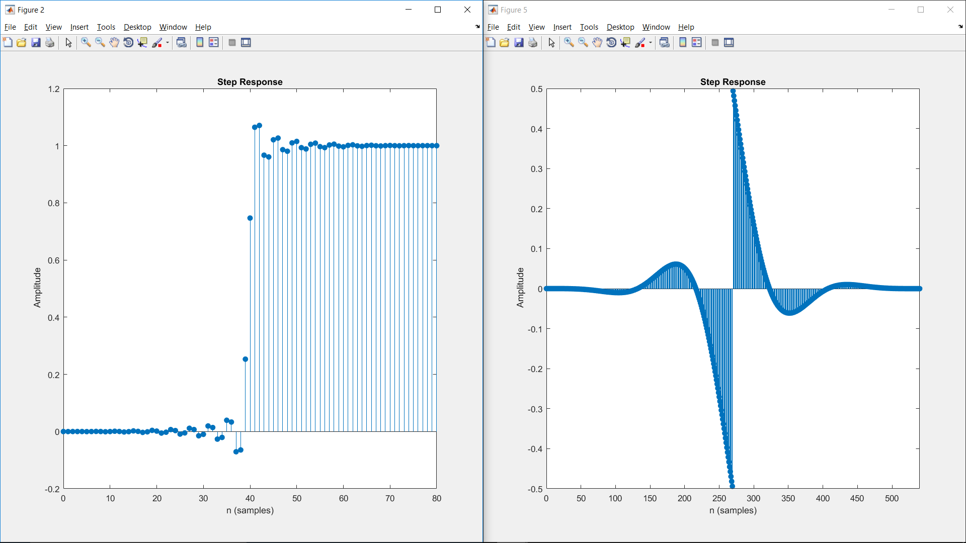
I am attaching the step responses of my lowpass filter (left) and highpass (filter) right, and I would like to understand, what did I do wrong? I have looked at the filtered signal and it looks good, it is delayed considerably, and I know FIR filters requires longer execution time, but I am working on it offline, as in not in real-time, and I think I optimized the frequency response, as I mentioned, pretty much, so if that phrase means what I think it means, then the signal is not preserved and its waveform is some how distorted, and I cannot have that for the intended application, so could some one please help me make sense of these seemingly contradictory understandings.

Thank you very much!

enter image description here

\$\endgroup\$
6
  • \$\begingroup\$ How did you sample that data you plot? Sampling rate? \$\endgroup\$
    – user16307
    Commented Nov 14, 2017 at 15:09
  • 1
    \$\begingroup\$ A filter that does not change the time-domain "waveform" of a signal in some way is a filter that does nothing at all. \$\endgroup\$ Commented Nov 14, 2017 at 16:13
  • \$\begingroup\$ The sampling rate is 81 sample/second, however, what is plotted here is the step response of the respective filters, it has nothing much to do with the sampling rate per se. The lowpass filter has 81 point kernel, the highpass filter has 541, for faster roll-off. That is definitely true James, sorry for confusing the two terms, although both are referred to as the signal, one means the signal inputted to the filter with the DC, interference and whatnot, whose waveform absolutely needs to be altered, the other is the actual physical signal that I want to have it intact. \$\endgroup\$
    – Albukhari
    Commented Nov 14, 2017 at 17:36
  • \$\begingroup\$ Sorry, 80, and 540 points, respectively. The step response confused me, again! \$\endgroup\$
    – Albukhari
    Commented Nov 14, 2017 at 17:45
  • 1
    \$\begingroup\$ A couple of things to note. First, FIR filters have linear (not constant) phase, i.e. the shift it not equal for all frequency components. Second, the frequency- and time-domain trade-off applies to any linear filter, analog or digital, and is a byproduct of convolution. \$\endgroup\$ Commented Jan 8, 2018 at 8:54

1 Answer 1

2
\$\begingroup\$

What you are seeing is not wrong at all. To illustrate this I have generated some plots that may illustrate the point.

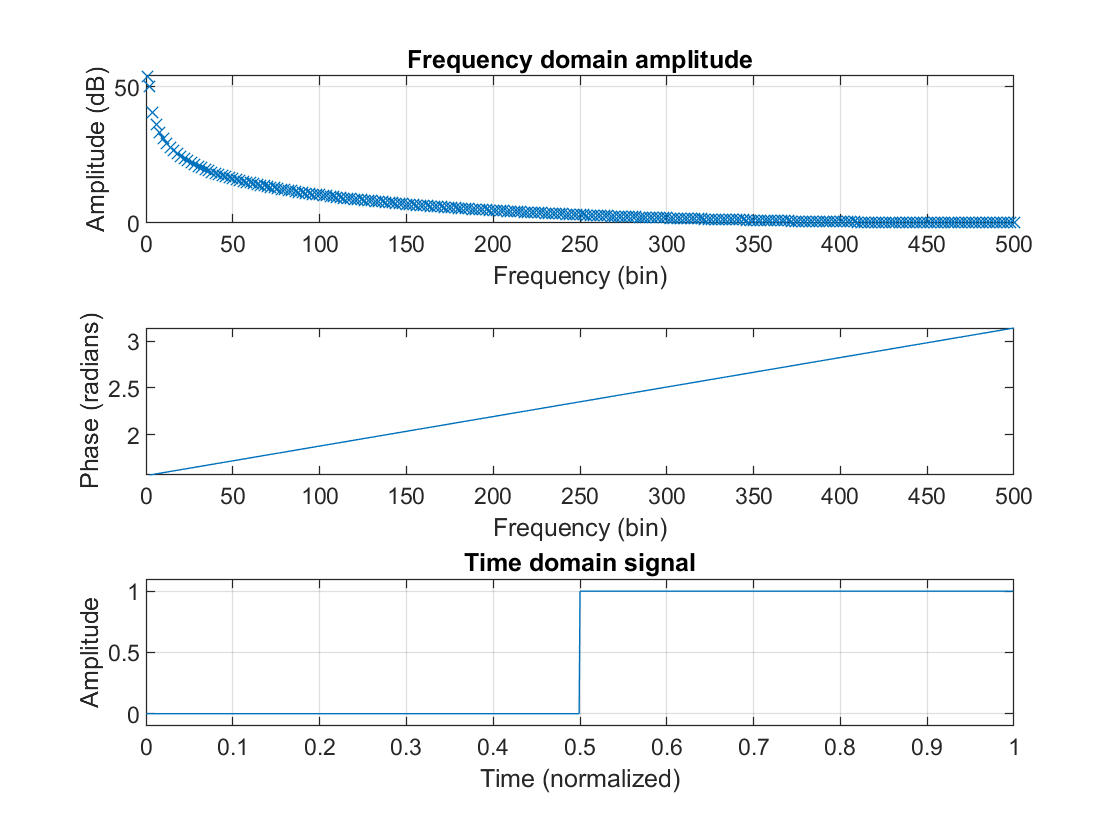
I decided to start from a signal that has many spectral components, namely a block pulse (the signal is assumed to be periodic). This signal is the unfiltered signal.

Unfiltered signal

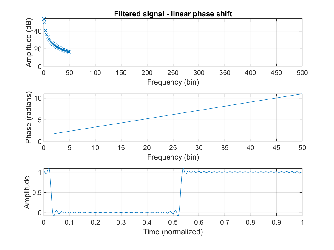
Now let's see what happens to that signal if we filter it perfectly. We cut off all spectral components after the 50th bin. Our filter will also introduce a linear phase shift.

Filtered signal with linear phase shift

A linear phase shift is added to the phase of the original signal, which causes a delay, in this case of about 30 samples.

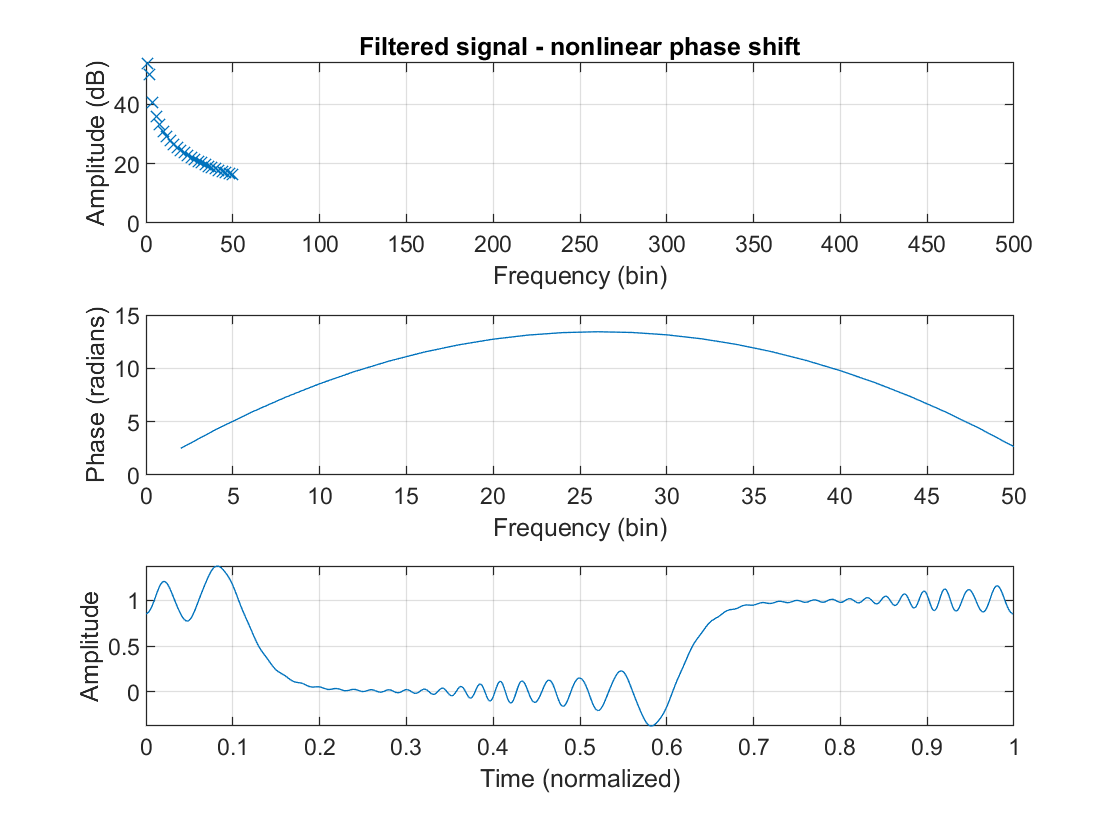
Now let's look at what happens when a severely nonlinear phase shift is introduced!

Filtered signal with nonlinear phase shift

It is immediately obvious that there is something off about the signal. The author of your book calls this "distorted". How should you interpret this?

In order to shift a spectral component, a sine, with a fixed delay \$t_d\$, we first need to determine what this means for that spectral component!

\$A\cdot \sin (2\pi f(t-t_d)) = A\cdot \sin (2\pi f - 2\pi f\cdot t_d)\$

\$\Rightarrow \phi = 2\pi f\cdot t_d\$

So in summary, in order to shift all spectral components by the same time delay, you need to shift them by a phase proportional to their frequency. The latter meaning that the phase shift needs to be linear.

As you can see, it does not necessarily mean that the waveforms look the same after filtering, because that is just what filters do. But, if you want to keep all spectral components lined up neatly in the time domain, you will need to enforce a linear phase shift.

\$\endgroup\$

Your Answer

By clicking “Post Your Answer”, you agree to our terms of service and acknowledge you have read our privacy policy.

Not the answer you're looking for? Browse other questions tagged or ask your own question.