0
\$\begingroup\$

This is the basic setup of what I'm going to do. Have a wire plugged into the mains that is then connected to a ON/OFF flip switch then goes on to the rest of my project. Want I want to do is to add an internal DC circuit supplied by a 9V battery that when detects that the switch is closed i.e. their is mains power going through the wire, a green LED will light and when there is no power, there's a red LED.

What should I do to achieve this? (I was thinking of using some sort of transistor) A circuit diagram would be great as well.

Thanks,

\$\endgroup\$
3
  • \$\begingroup\$ A hall effect switch is what you want. \$\endgroup\$
    – Passerby
    Commented Mar 25, 2016 at 19:13
  • \$\begingroup\$ @TheTinkerMan: You need to be a bit more specific. Do you want to detect current or voltage? For example, if there is nothing connected at the other end of this wire do you want the light to turn on? Alternatively do you want to sense that current is flowing to a load? If so, what is the threshold you wish to detect. \$\endgroup\$
    – Transistor
    Commented Mar 25, 2016 at 19:21
  • \$\begingroup\$ en.wikipedia.org/wiki/Current_sensor \$\endgroup\$
    – user65586
    Commented Mar 25, 2016 at 19:21

2 Answers 2

2
\$\begingroup\$

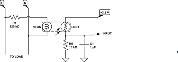
If you just want to detect mains on / off then a neon-LDR optocoupler provides a safe way to do it. I offer this as an incomplete answer as I have not tested it.
schematic

simulate this circuit – Schematic created using CircuitLab

Neons are relatively low-power and a 1/4 W 220 kΩ resistor is all that's required to light it from 230 V mains. An LDR (light dependent resistor) is used on the low-voltage side. In the schematic above I have added a 1 uF capacitor to maintain the 'mains present' signal during the zero-cross.

Neon optocouplers were used by Fender guitar amplifier vibrato circuits and are still available. A web search for 'neon optocoupler' shows up some more recent implementations for modern micros for 'mains presence' rather than the usual zero-cross applications.

Fender neon optocoupler - http://shop.sonnywalton.com

Neon optocoupler for Fender vibrato. Note use of opaque heatshrink to prevent ingress of stray light. The neon appears to be on the left with bulb point visible pointing to the LDR on right.

I suggest that this idea is worth consideration. The neon optocoupler can be home-made using a regular neon, an LDR and black heatshrink.

\$\endgroup\$
2
  • \$\begingroup\$ Great Thx that is exactly what I need! \$\endgroup\$
    – user104527
    Commented Mar 25, 2016 at 21:48
  • 1
    \$\begingroup\$ Thanks for accepting this answer. Do keep the mains wiring completely separate from your low voltage wiring. Use the neon-LDR as an optical bridge between the two systems. \$\endgroup\$
    – Transistor
    Commented Mar 25, 2016 at 22:30
0
\$\begingroup\$

Have you thought about just using a neon indicator, or maybe a switch which incorporates one, like this.

A lot easier and cheaper than a PP9 as well.

\$\endgroup\$

Your Answer

By clicking “Post Your Answer”, you agree to our terms of service and acknowledge you have read our privacy policy.