3
\$\begingroup\$

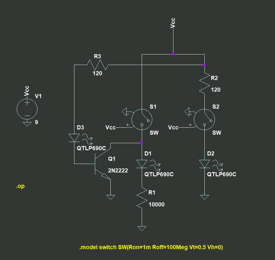
I have 2 switches in total, one connects to a red LED, and another connects to a green LED. Both switches turn on and off their individual LEDs. When both switches are turned on, only a yellow LED must be on, and the rest should be off.

I have a circuit below, it doesn't seem to work for me. What seems to be the problem here?

I'm using LTspice. The LED part number is QTLP690C, transistor 2N2222. I have tried changing the resistor value but it still doesn't work.

enter image description here

\$\endgroup\$
5
  • \$\begingroup\$ Why don't you design it with logic gates first then evolve it into something using transistors. Do you understand logic gates? Your schematic looks fatally flawed to me in that I'd restart from scratch using logic. \$\endgroup\$
    – Andy aka
    Commented Feb 20, 2023 at 11:32
  • \$\begingroup\$ Yes I do, but I have made it work halfway in which when i replaced the Yellow LED with a diode and both switches are on, it turns off the Red and Green LED. Just that when the Yellow LED is in the circuit, it turns on with the Red LED, and interfering the whole circuit. I've tried recreating the circuit in real life and the same results shows. \$\endgroup\$
    – Leewchaha
    Commented Feb 20, 2023 at 11:38
  • \$\begingroup\$ I have no idea which is red, yellow or green in your schematic and, is "halfway" working any evidence that you are on the right track to making it fully working? I don't think it is. My view is that you start from a proper logic schematic and evolve to transistors and switches. \$\endgroup\$
    – Andy aka
    Commented Feb 20, 2023 at 11:42
  • \$\begingroup\$ Oh, alright, thanks for the suggestion. Ill try to start from logic gates as how you said it. \$\endgroup\$
    – Leewchaha
    Commented Feb 20, 2023 at 12:15
  • 2
    \$\begingroup\$ use color mixing ... get a red/green dual LED ... connect as before ... both switches ON will make yellow \$\endgroup\$
    – jsotola
    Commented Feb 20, 2023 at 17:14

6 Answers 6

6
\$\begingroup\$

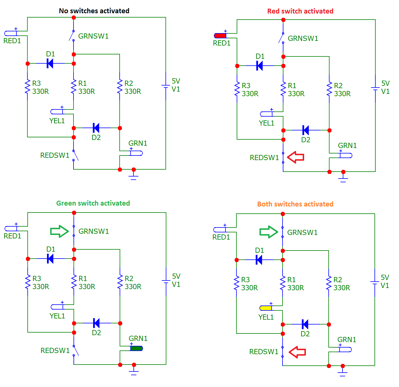
I have 2 switches in total, one connects to a Red LED, and another connects to a Green LED. Both switches on and off their individual LEDs. But when both switches are turned on, only a Yellow LED must be on, and the rest should be off.

If you begin with logic gates as I did, you can then start to evolve solutions that you can easily test in a simulator like microcap. Here's what I ended up with: -

enter image description here

It's worth using a simulator that has an animation mode (like microcap) because, well.., it's really easy and saves you endlessly trying things out on breadboard. I managed to evolve a solution that doesn't use transistors. There may be a simpler solution to be found?

\$\endgroup\$
3
  • 1
    \$\begingroup\$ "There may be a simpler solution to be found?" Don't think so. Nice. \$\endgroup\$
    – AnalogKid
    Commented Feb 24, 2023 at 1:57
  • 1
    \$\begingroup\$ Clever solution! \$\endgroup\$ Commented Feb 24, 2023 at 3:51
  • 1
    \$\begingroup\$ Thank you ! I've tried starting with logic gates as you've mentioned and I've created one with 7 bjt transistors, your's are much better as it doesn't require one. \$\endgroup\$
    – Leewchaha
    Commented Feb 26, 2023 at 7:16
4
\$\begingroup\$

The basic idea

Almost every time I see a problem related to switching LEDs I manage to solve it with the help of a powerful circuit idea. I came up with it in the 80's and even managed to patent it... but later I saw it being used in TTL gates and other circuits. The idea is as follows:

If we connect several diode elements with different forward voltages in parallel, the current passes through the element with the lowest forward voltage.

This allows switching between two diodes only with a simple SPST switch and not with a SPDT switch or two SPST switches as is the straightforward solution. Run the simulation below to try it:

  • with "ideal" diodes D1, D2 and D3 having different forward voltages of 1 V, 2 V and 3 V respectively
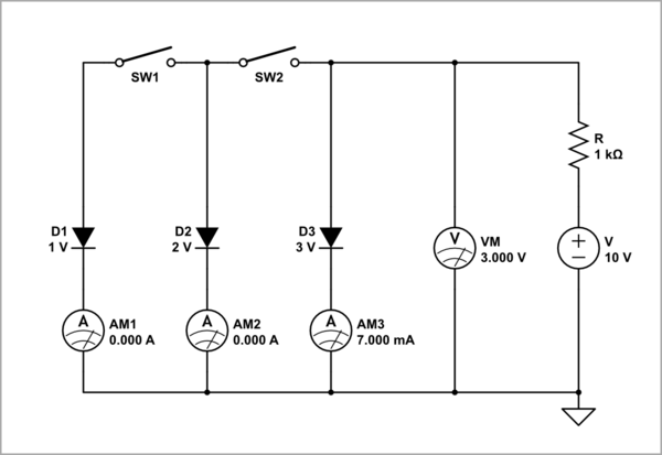
schematic

simulate this circuit – Schematic created using CircuitLab

  • with diode strings having different total forward voltages
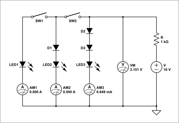
schematic

simulate this circuit

The implementation

Here the problem was more complicated because the OP required that a combination of switches in series be used as well. Going over the different combinations in my head I suddenly got the idea of ​​using a bridge. I wish I had remembered how I came up with this idea... and told it here... but I was quite excited and I cannot remember now. Here is the schematic.
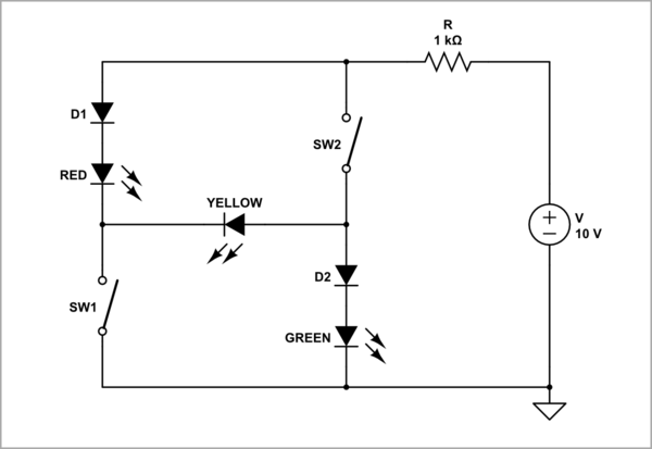
schematic

simulate this circuit

As you can see, the forward voltage of the RED and GREEN diodes is artificially increased by connecting ordinary diodes (D1, D2) in series (these diodes become redundant if you use LEDs with different forward voltages).

The operation

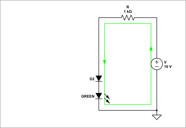
SW1 = OFF; SW2 = ON

The current is diverted through the D2 and green LED and only it lights up.
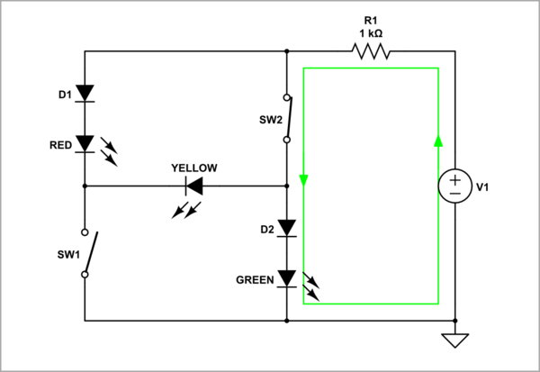
schematic

simulate this circuit

The other diodes (D1, RED and YELLOW) do nothing and can be removed from the circuit.
schematic

simulate this circuit

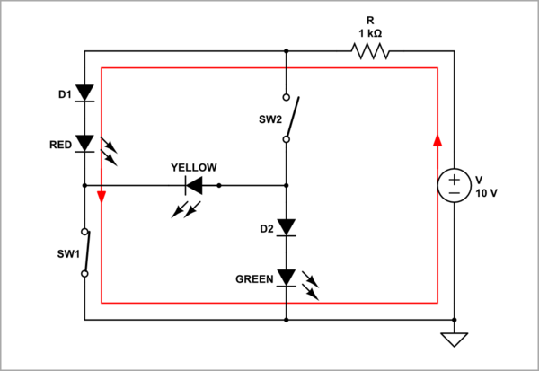
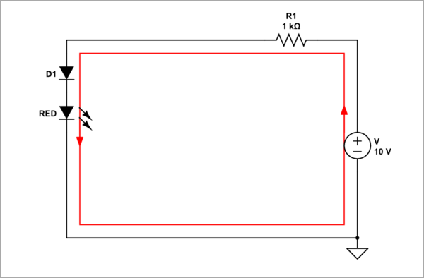
SW1 = ON; SW2 = OFF

The current is diverted through the D1 and red LED and only it lights up.
schematic

simulate this circuit

The other diodes (D2, GREEN and YELLOW) do nothing and can be removed from the circuit.
schematic

simulate this circuit

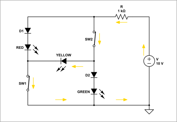
SW1 = ON; SW2 = ON

The current is diverted through the yellow LED and only it lights up.
schematic

simulate this circuit

The other diodes (D1, D2, RED and GREEN) do nothing and can be removed from the circuit (or drawn in pale gray).
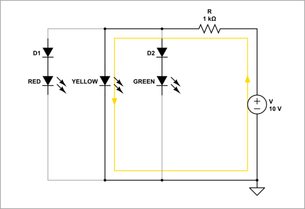
schematic

simulate this circuit

Evaluation of the solution

Let's finally appreciate this circuit solution based on the "self-switching diodes" idea.
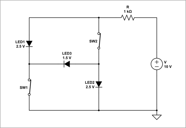
schematic

simulate this circuit

  • If we assume that the two switches, the three LEDs with a (common) resistor in series and the power supply are already there... then the circuit consists of "nothing"! This is the power of the inventive idea compared to a straightforward design solution.

  • Since the current is steered between the diodes, only one LED current is consumed (hence the name "current steering" of thus technique).

  • The only requirement is that LED3 must have less forward voltage than LED1 and LED2 (in the diagram above, I have simulated this with "ideal" diodes of different forward voltages). Well, if we cannot find such LEDs, we will settle for using two diodes.

"Non-bridge" diagram

The circuit diagram can also be drawn not as a bridge configuration; for some it might be more understandable that way.
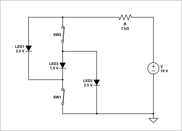
schematic

simulate this circuit
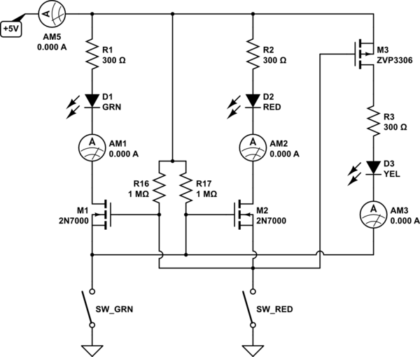
\$\endgroup\$
1
\$\begingroup\$

Here is a solution that uses the fact that an AND gate with inverted inputs is a NOR gate.

It does not depend on tricks with LED Vf differences which can work out less than satisfactory in practice.

schematic

simulate this circuit – Schematic created using CircuitLab
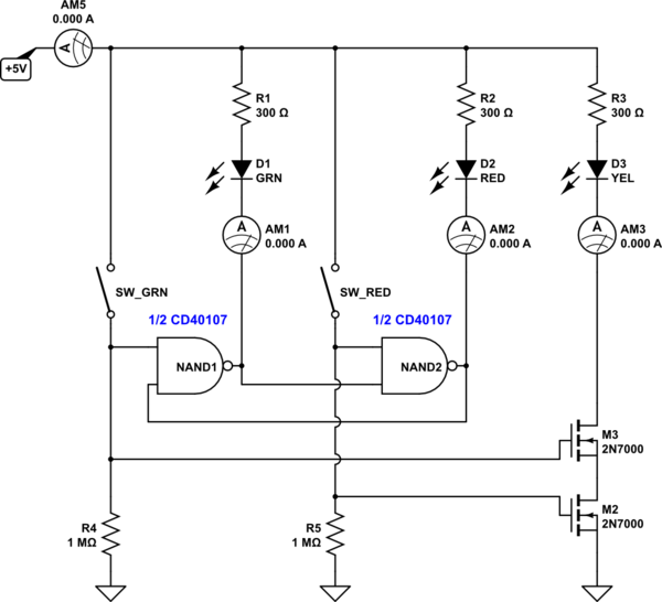
\$\endgroup\$
0
\$\begingroup\$

enter image description here

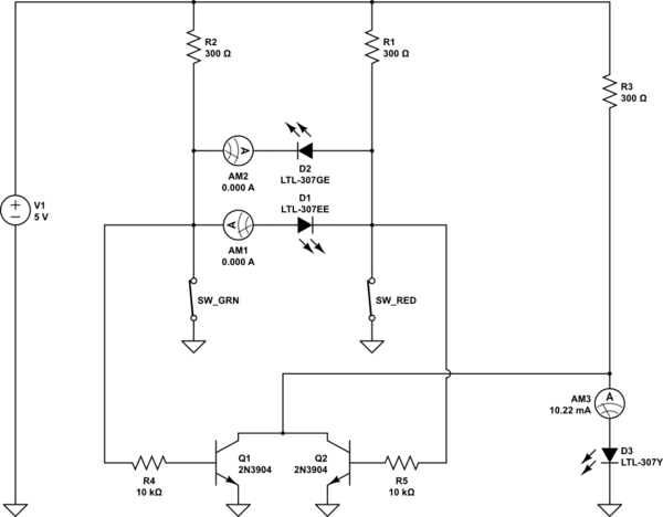
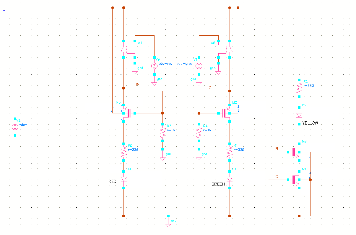
There are many solutions possible. Here is one implemented using MOSFETs. In your schematic, I assume D3 is yellow. If VCC is sufficiently high, it will be always ON irrespective of S1, S2 and there will be very high current through Q1 because there is no resistor to limit the current.

Edit: The high current through Q1 is if switch S1 is also ON.

One advantage of the scheme proposed here is that there is minimal wastage of current.

\$\endgroup\$
0
\$\begingroup\$

The logic can be implemented with discrete CMOS devices. The LED currents and forward voltages are independent of each other.

schematic

simulate this circuit – Schematic created using CircuitLab
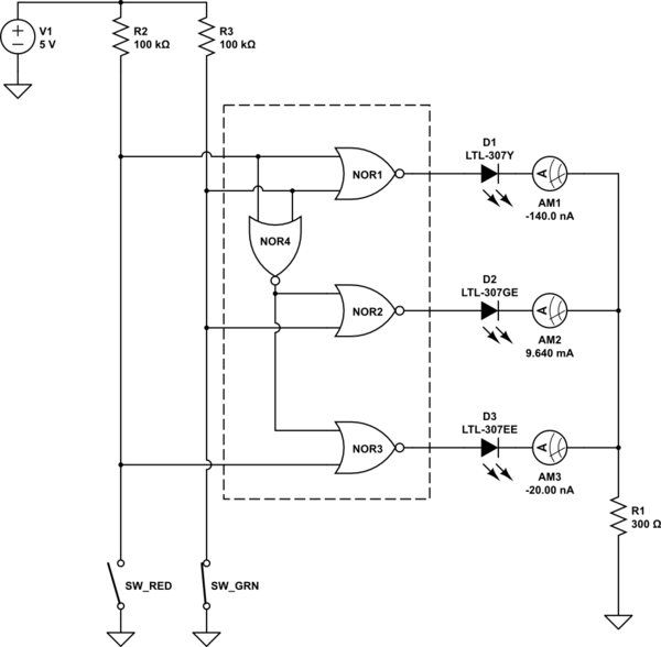
We can also use high-current open drain NAND drivers. Two such drivers come in an 8-pin package.

schematic

simulate this circuit

Both circuits above have very low idle current consumption, mostly determined by the leakage current of the MOS devices. Typical consumption of each at room temperature should be ≈1uA.

\$\endgroup\$
0
\$\begingroup\$

If you want to use a single quad-gate package (not in the spirit of the homework question), this uses a 74HC02 quad-2 input gate package. Draws only leakage current with the switches off so suitable for battery operation. Duplicating the NOR1 as NOR4 allows heavy loading on the LED driver.

schematic

simulate this circuit – Schematic created using CircuitLab

\$\endgroup\$

Your Answer

By clicking “Post Your Answer”, you agree to our terms of service and acknowledge you have read our privacy policy.

Not the answer you're looking for? Browse other questions tagged or ask your own question.